LulzBot
Printhead
2,000+ Units
Identified a platform limitation in a widely-deployed industrial 3D printer. Reverse-engineered the entire machine in SolidWorks from scratch. Custom billet aluminum hobbing fixture, ground-up printhead redesign, electronics workaround with a self-cooling thermal management solution. Scaled to 2,000+ units across three SKUs. Out-competed the OEM's own subsequent release on reliability and serviceability.
The Platform, the Problem, and Getting Inside the Machine
The LulzBot TAZ was a genuine workhorse in industrial rapid prototyping environments. Large build volume, proudly designed and manufactured in the USA, and built on a fully open-source philosophy: every STL file for every component published on their website, repairable in the field without sending the printer in. For professional operators running print farms or prototyping labs, these were meaningful advantages over the consumer-grade alternatives.
The limitation was filament. The TAZ uses 2.85mm, a legacy standard being left behind as the broader ecosystem converged on 1.75mm. Availability of 2.85mm was tightening and cost was rising. For operators already invested in LulzBot infrastructure, the choice was to accept the constraint or replace the entire platform.
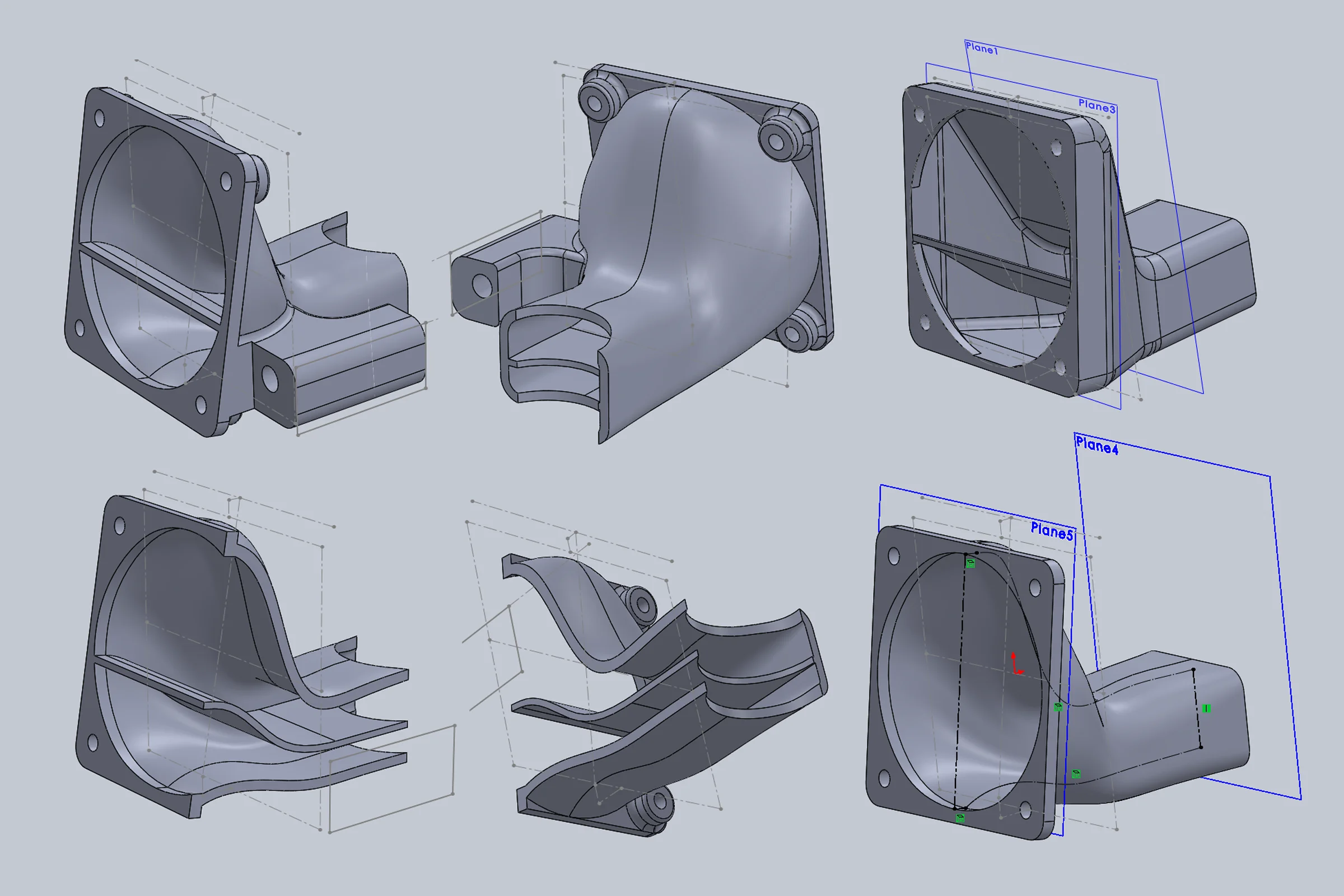
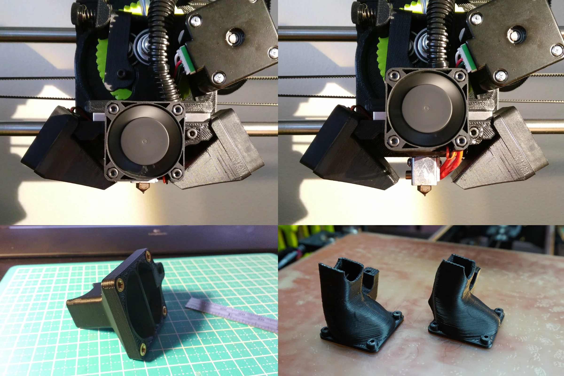
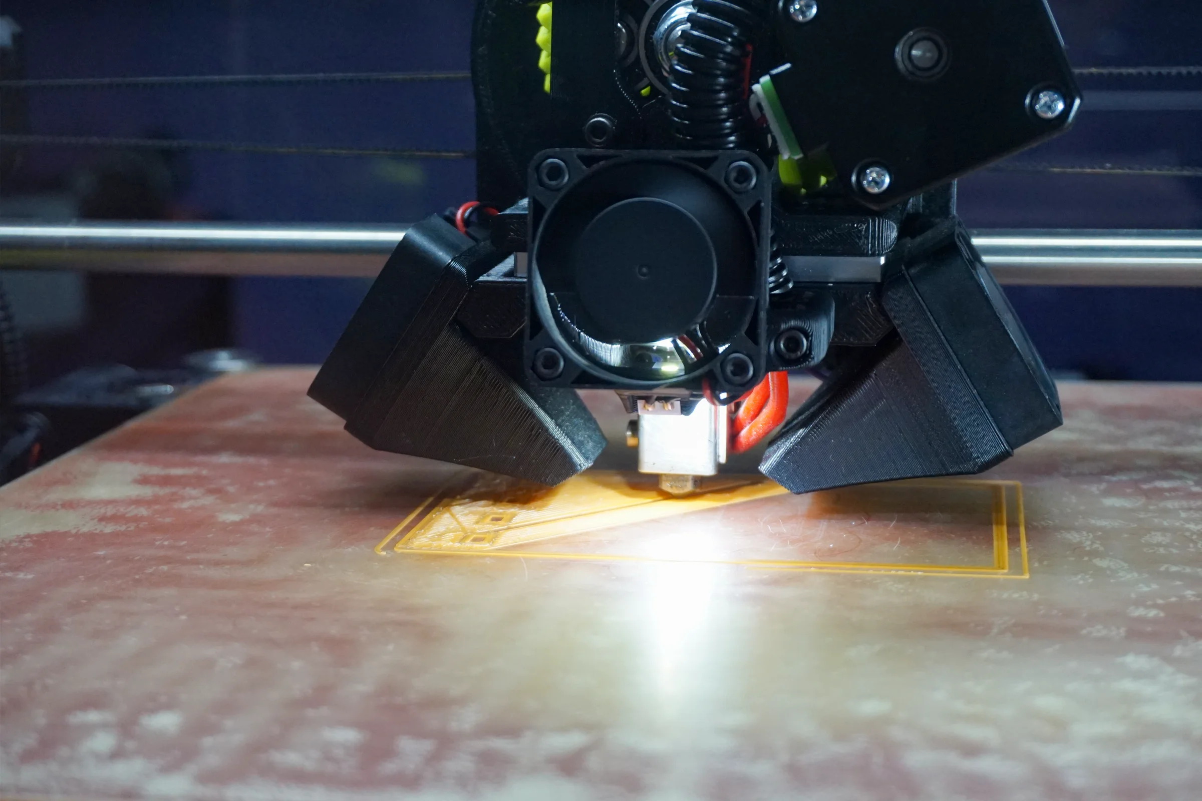
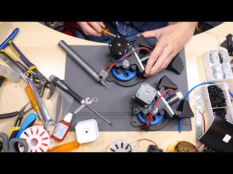
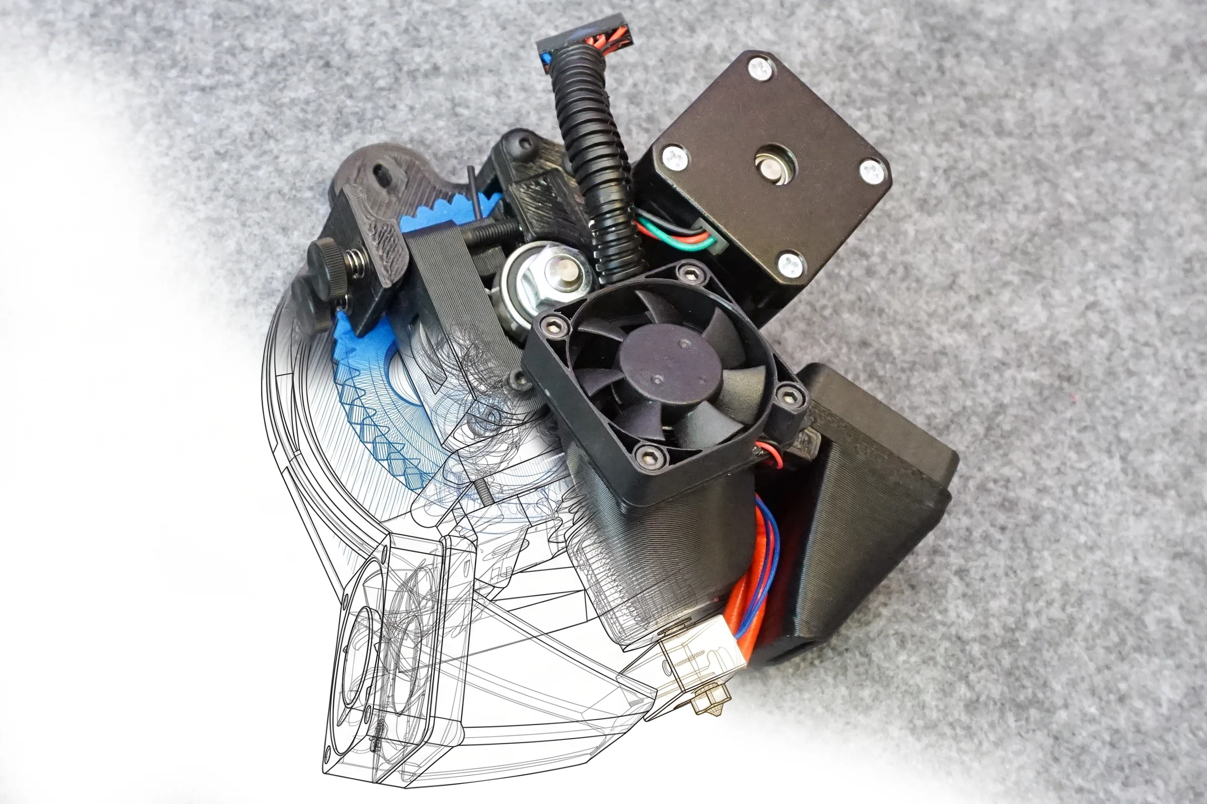
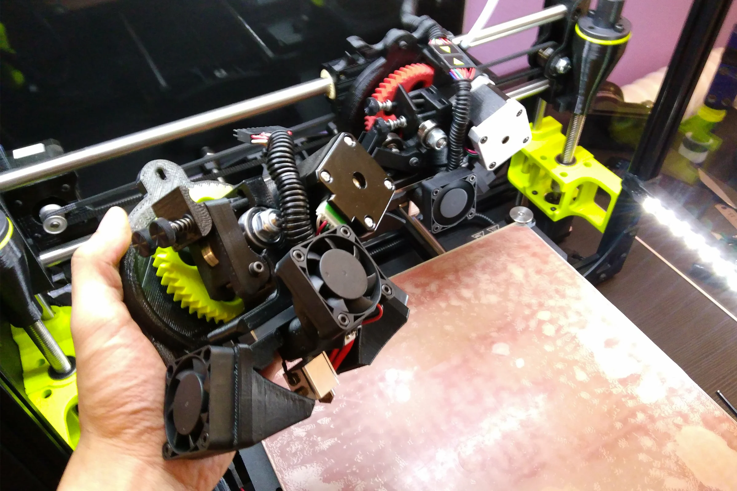
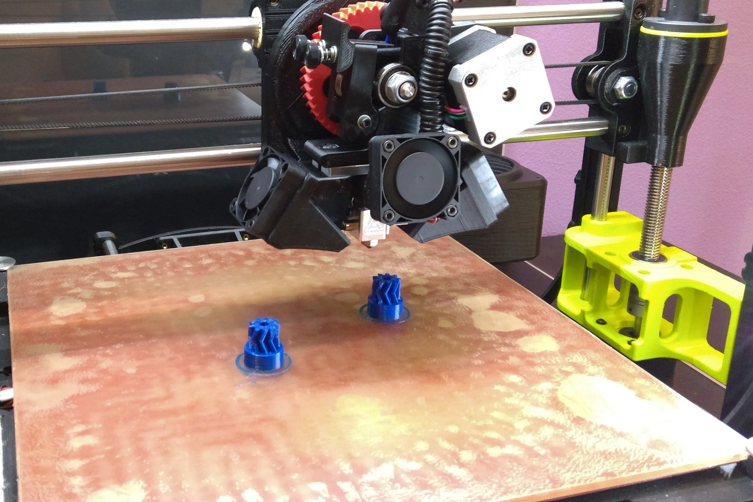
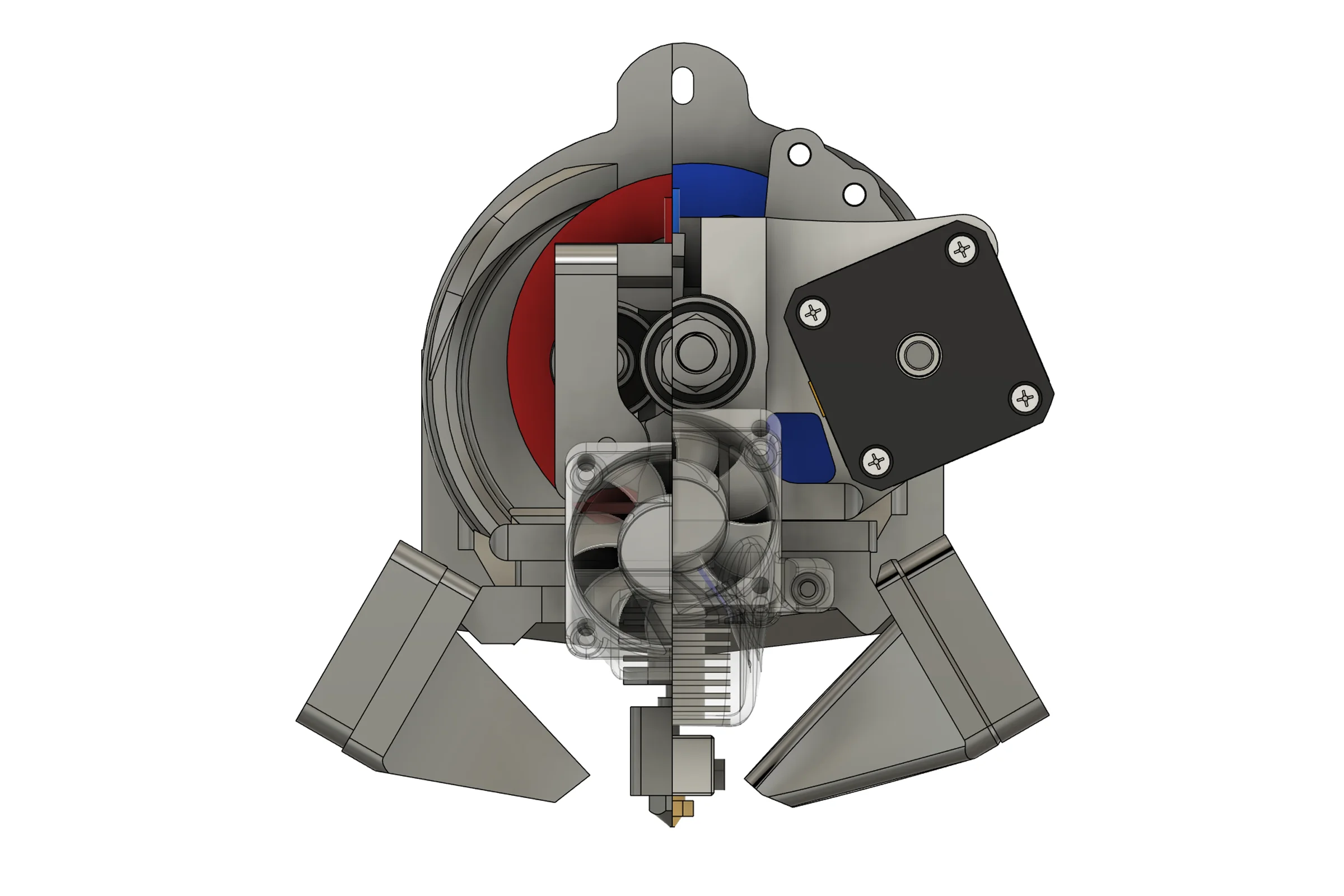
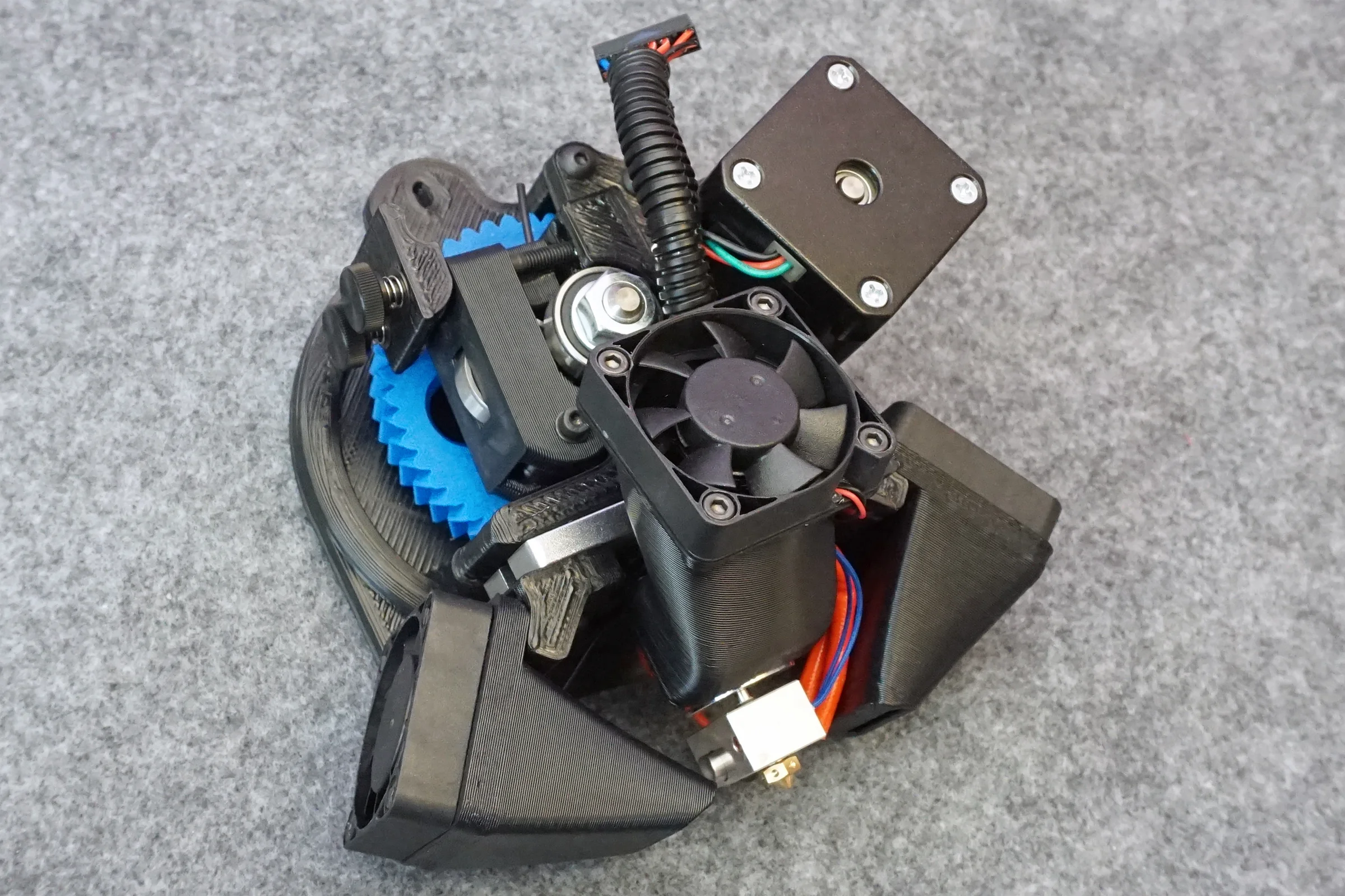
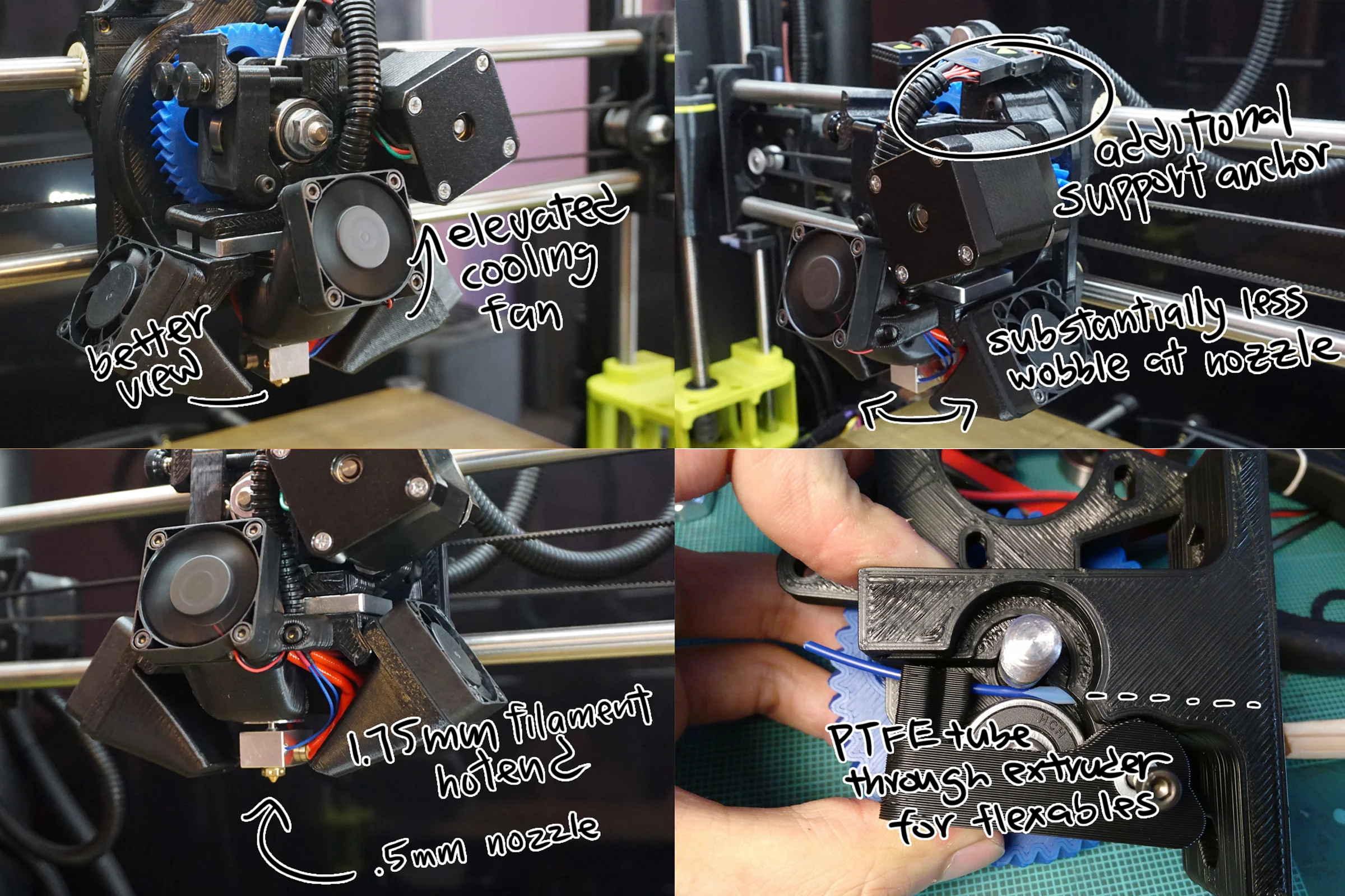
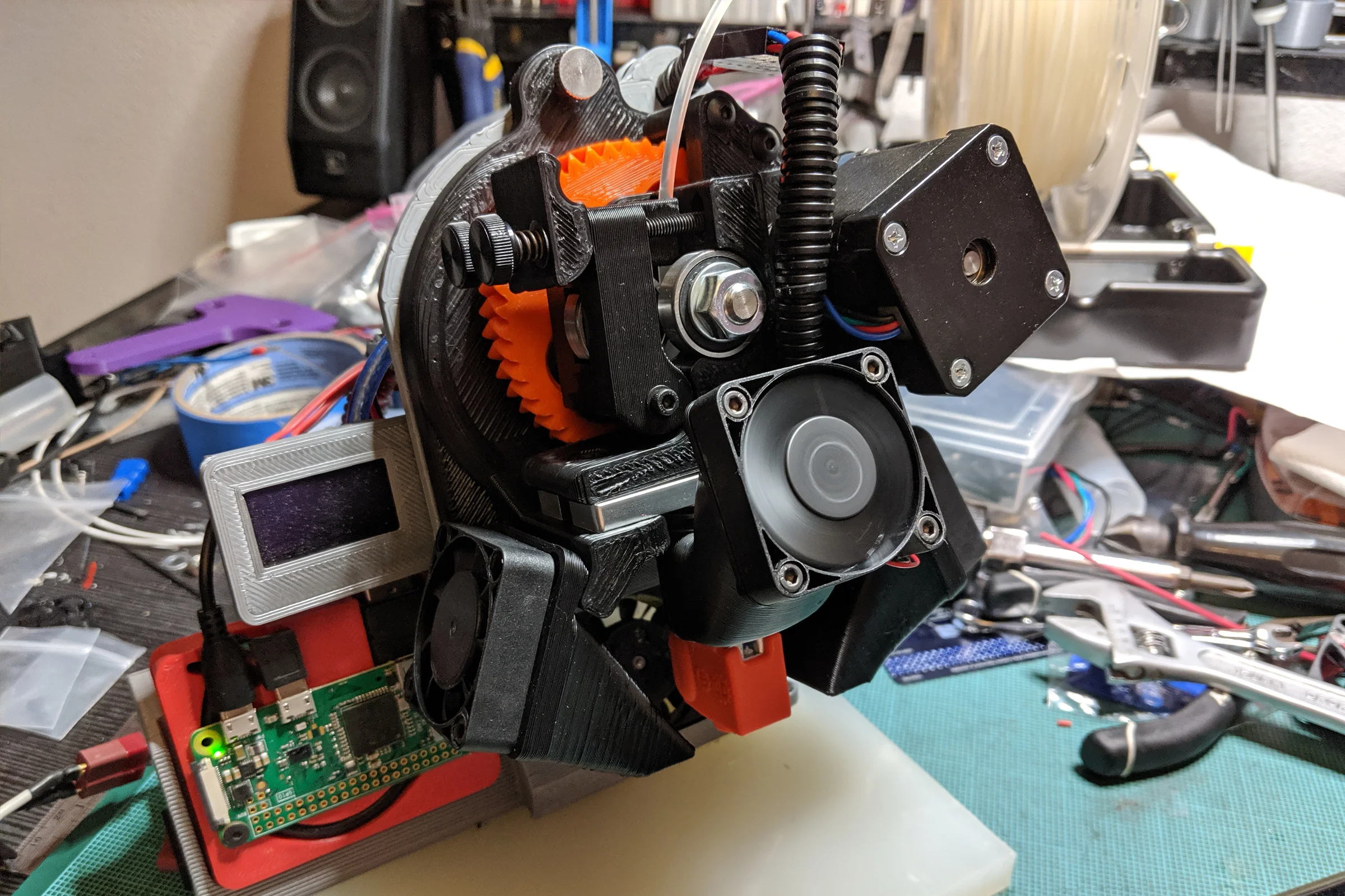
It started with a simpler frustration: the stock cooling fan blocked direct nozzle visibility during printing, particularly on the critical initial layers when the printhead is closest to the bed. I redesigned the fan duct in SolidWorks, repositioning the fan as high as the geometry allowed and opening the front face completely. The nozzle was now fully visible with enough clearance to manually tweezer away stray filament extrusions during the initial layer. That modification was the door into the machine. The TAZ had an interchangeable printhead system, and once inside it became clear the filament constraint was solvable too. The architecture for a solution already existed. It just needed someone to build it.
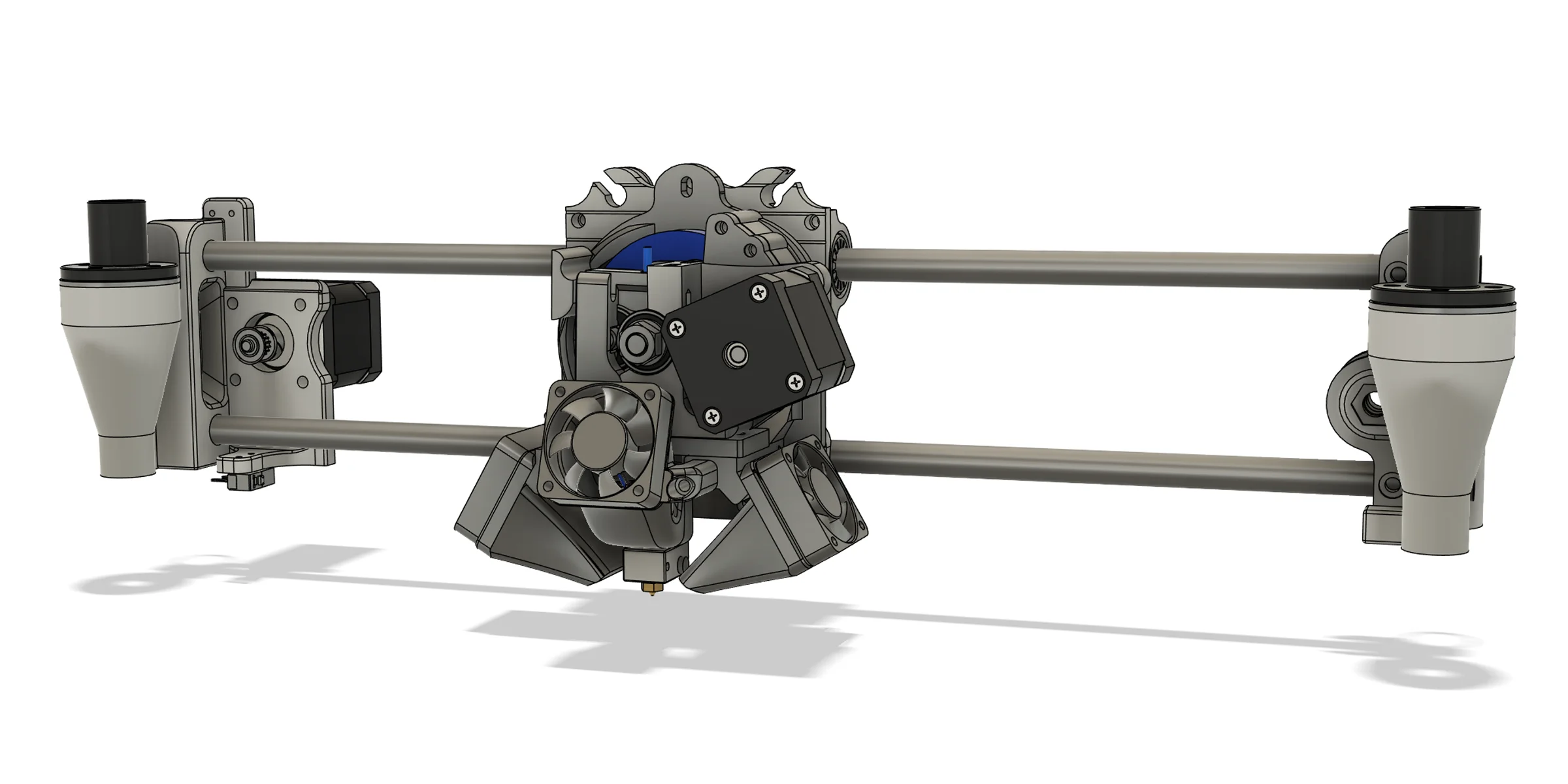
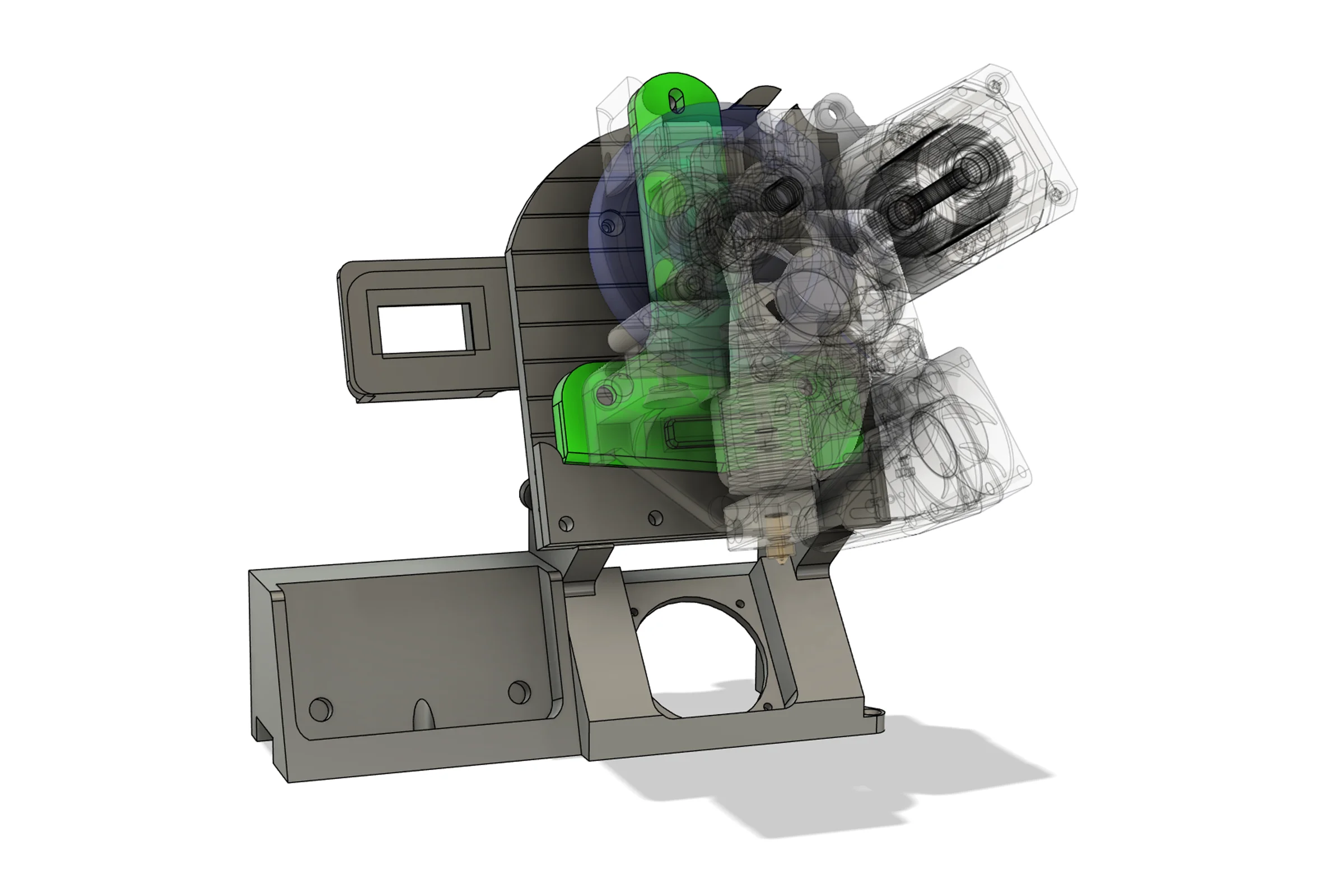
LulzBot's open-source commitment meant every component STL was publicly available. Useful for self-repair, but not useful for parametric design work. Knowing I would be modifying and developing against this platform extensively, I downloaded every STL and recreated the printhead and the entire X-axis gantry as a fully parametric SolidWorks assembly (later exported to Fusion360), cross-referenced against physical measurements from the machine sitting next to me.
This was a substantial upfront time investment. The return was precise understanding of the machine and a digital environment where any modification could be immediately evaluated for fitment and interference. Every printhead iteration that followed was designed against this parametric assembly. Understanding not just what each component was, but why it was that specific geometry and what constraints it was responding to, allowed me to iterate through every subsequent improvement with much higher efficiency and precision.
The Hobbed Drive: Finding the Geometry
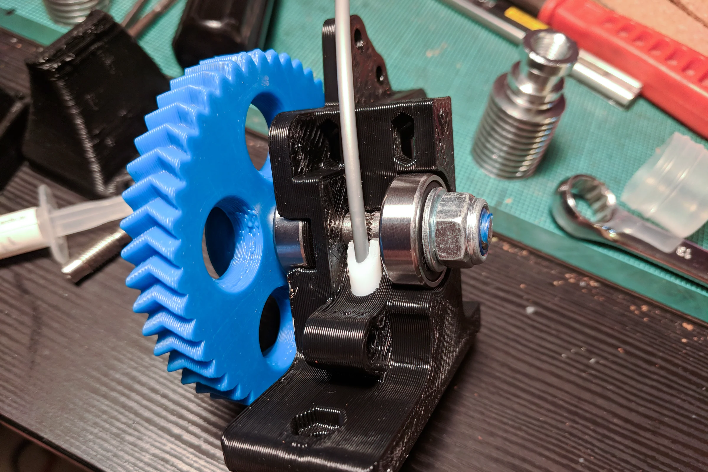
The hobbed drive bolt is a steel bolt with teeth machined into a section of it that grip filament under spring-loaded pressure, feeding it into the hotend. The original was sized for 2.85mm filament. A 1.75mm filament requires a completely different tooth geometry: different depth, count, and profile. Too shallow and the bolt slips under load. Too deep and it chews through filament rather than driving it.
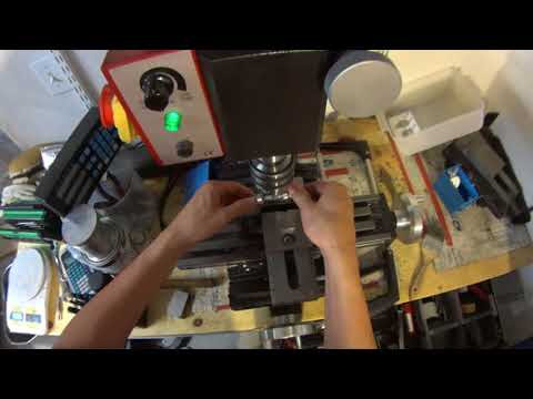
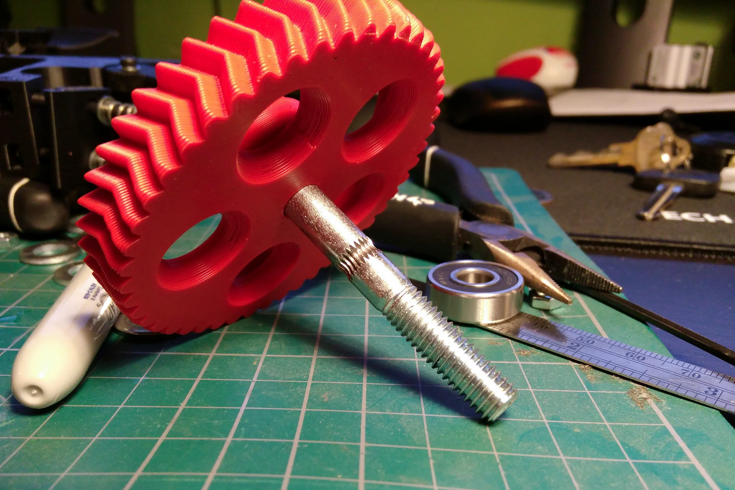
I set up a crude rotating fixture by clamping two skateboard bearings directly into the mill vise, which held the bolt and allowed it to be rotated between passes. Using every thread tap from M2 to M10, I systematically worked through tooth depth, count, and profile combinations, isolating one variable at a time. The iteration was entirely physical. Each variant went into a test printhead, ran filament at multiple temperatures and feed rates, and was evaluated for grip consistency and filament marking pattern. The winning geometry was clear within the test matrix. Getting to that answer required building the tooling first, not just modeling geometry in CAD.
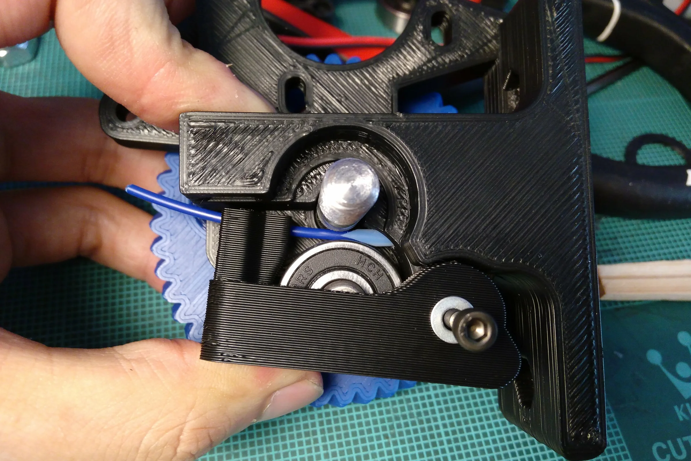
The hobbed drive bolt doesn't feed filament directly into the hotend. There is a short gap between the bolt and the hotend entry. In the original design that gap was not tightly constrained, allowing filament to buckle under drive pressure, particularly with flexible materials. I redesigned this section to incorporate a strategically cut PTFE tube liner bridging the full path from drive bolt to hotend entry. This also reduced friction in addition to fully constrained the filament path, and made the printhead capable of running flexible filaments reliably, something notoriously difficult to achieve in 1.75mm filaments.
The Jig System: Four Purpose-Built Production Tools
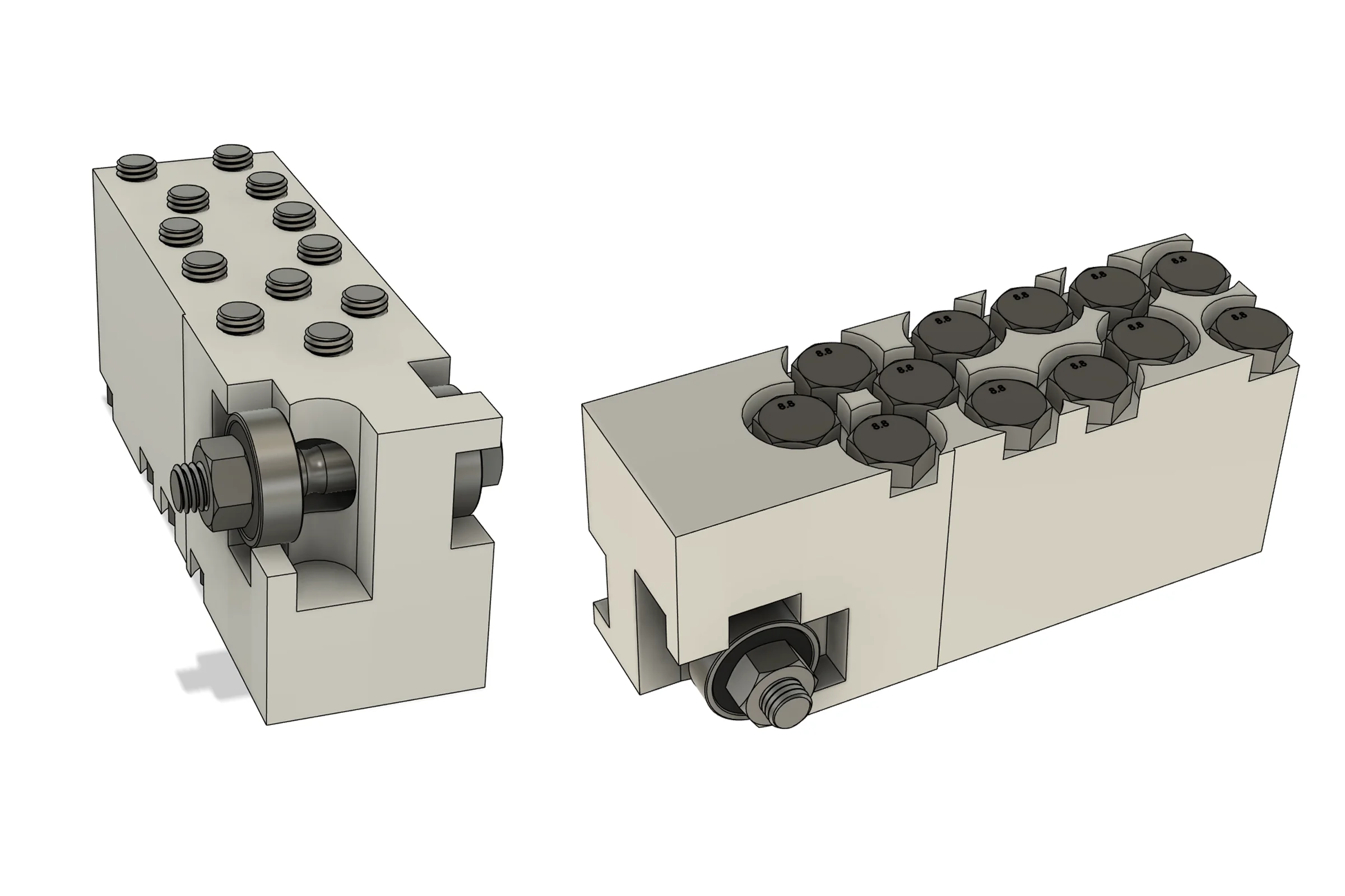
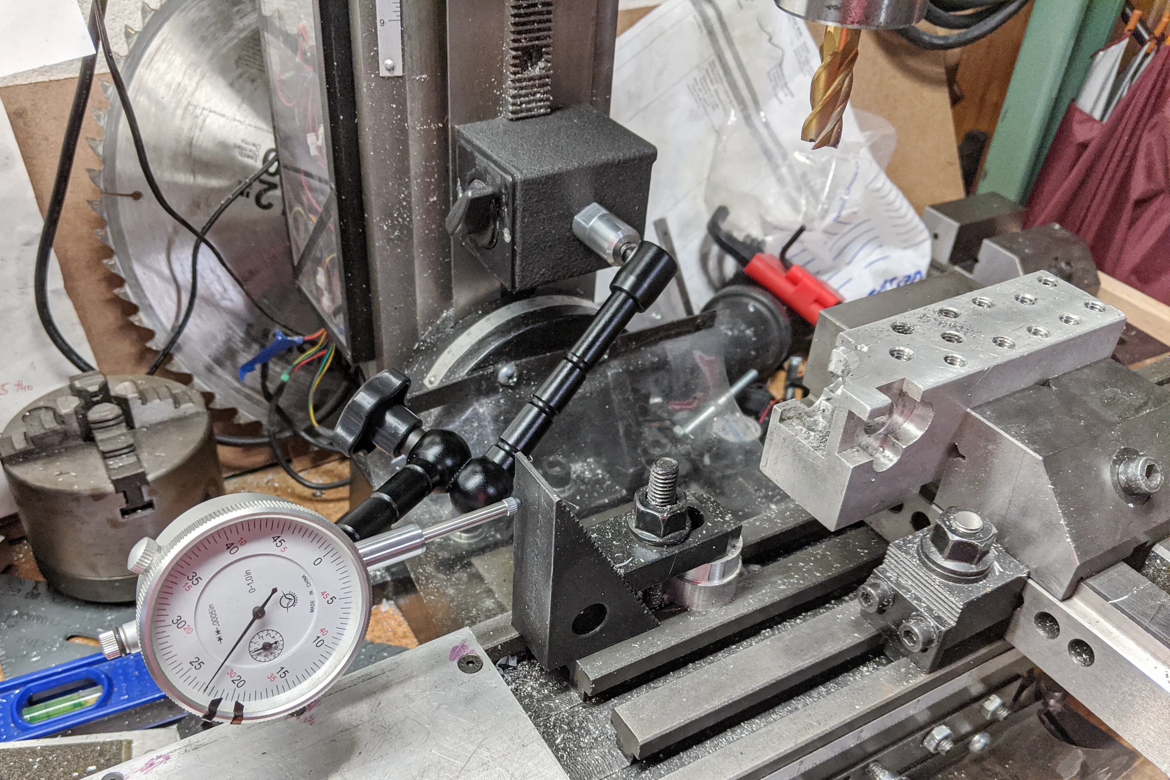
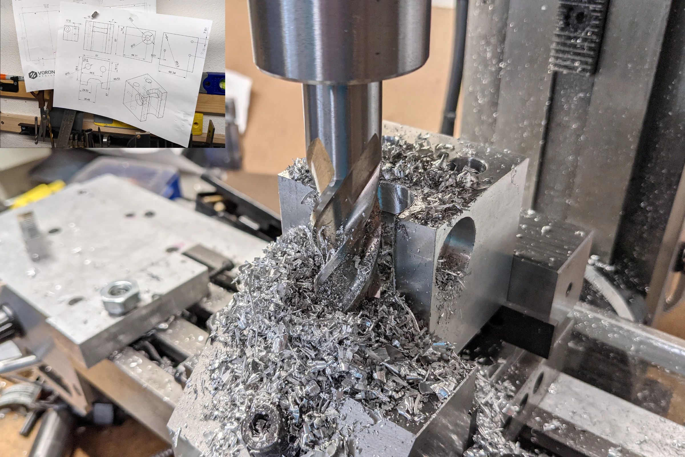
Once the winning tooth geometry was established, the next problem was repeatability at scale. The skateboard bearing fixture was a proof-of-concept, not a production tool. The first proper jig was milled from scrap aluminum and designed to hold multiple bolts simultaneously, one setup: cut all bolts to correct length in one pass, then clamp the same jig into the mill from the other end to hob the teeth. One fixture, two operations, consistent geometry across every bolt in the batch. The hobbing step still required holding a powered drill to rotate the bolt at a steady speed while the mill cut the tooth profile, repeatable enough, but a manual operation that capped throughput.
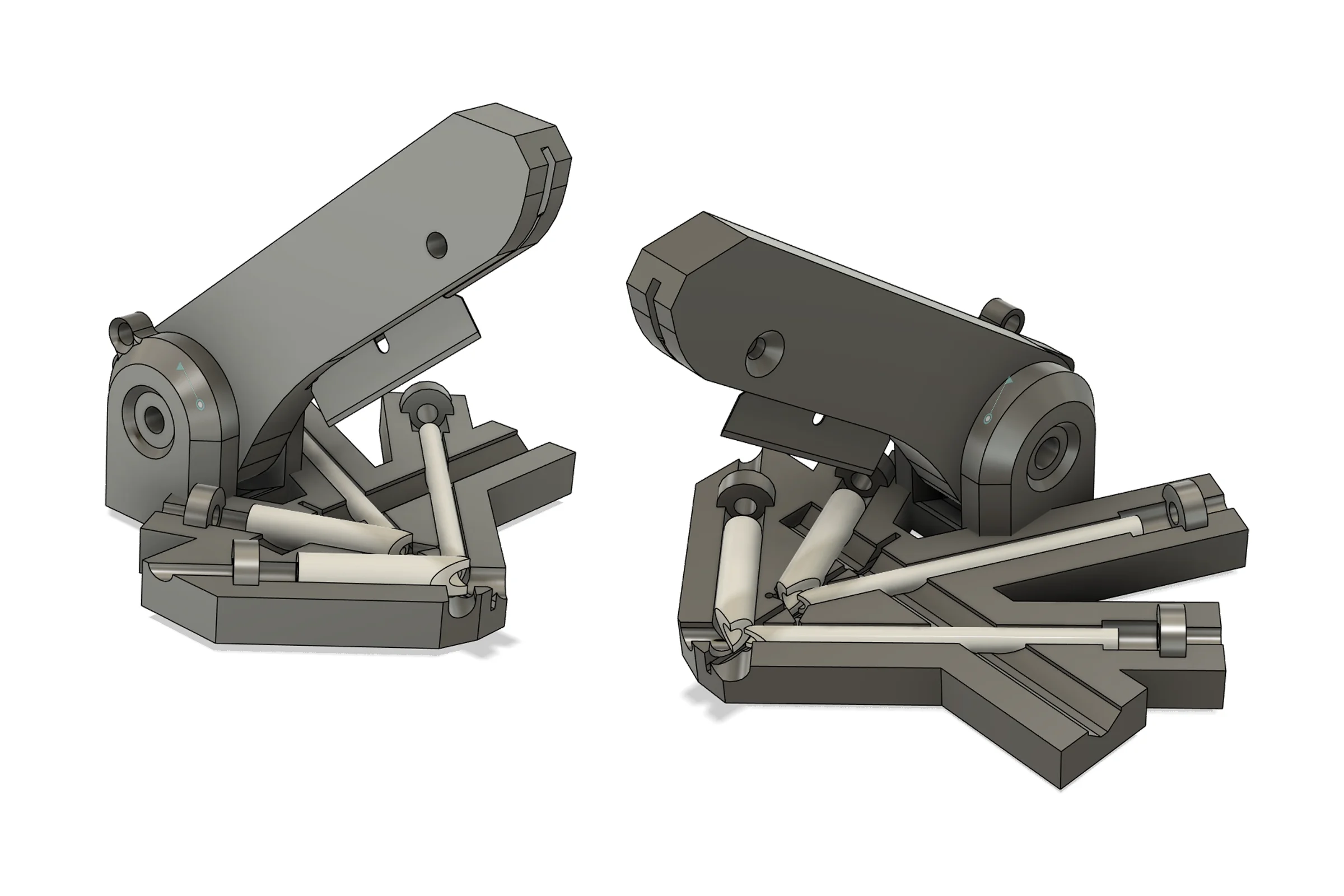
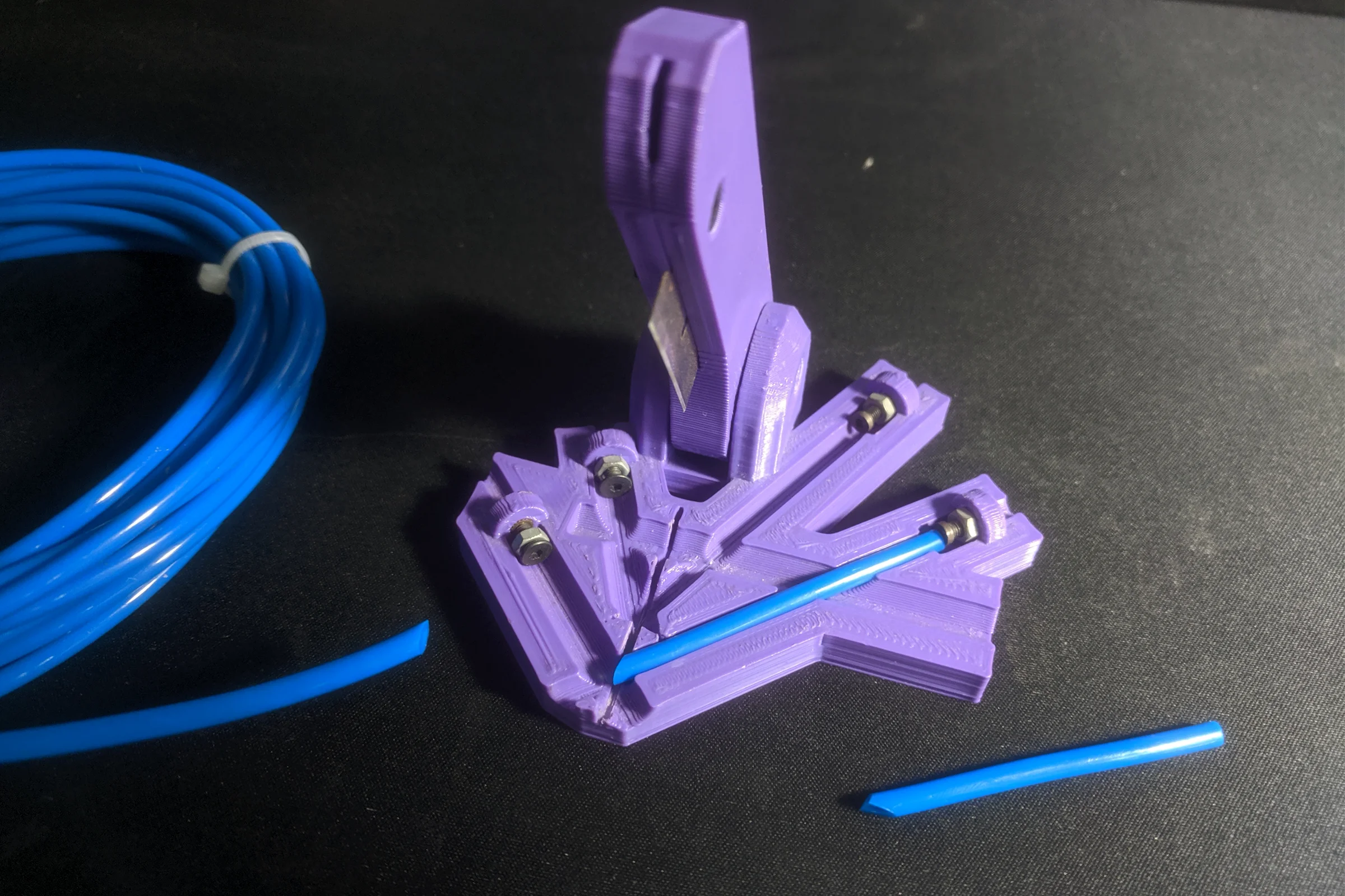
The PTFE tube that constrains the filament path between drive bolt and hotend entry also required custom tooling. The tube needed two precise angle cuts to minimize the unsupported filament gap as tightly as possible, critical for driving flexible filaments without buckling. I designed and 3D printed a four-slot cutting jig with a skateboard bearing on the cutting arm to eliminate lateral slop in the blade, ensuring each cut lands at the same location and angle every time. Two slots per side: the right side cuts PTFE tube to spec for 1.75mm filament, the left side for 2.85mm. First slot on each side cuts to length and makes the first angle cut. Second slot makes the final angle cut. One jig, both filament sizes.
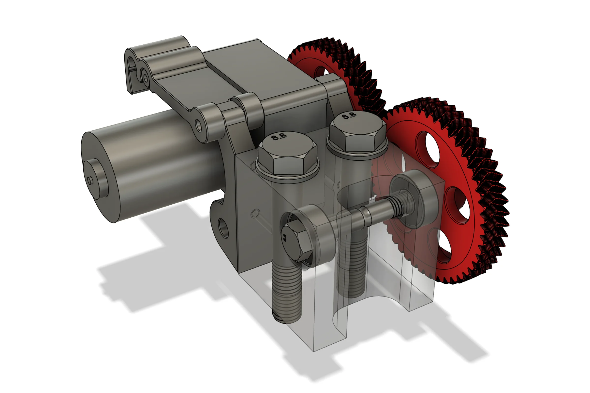
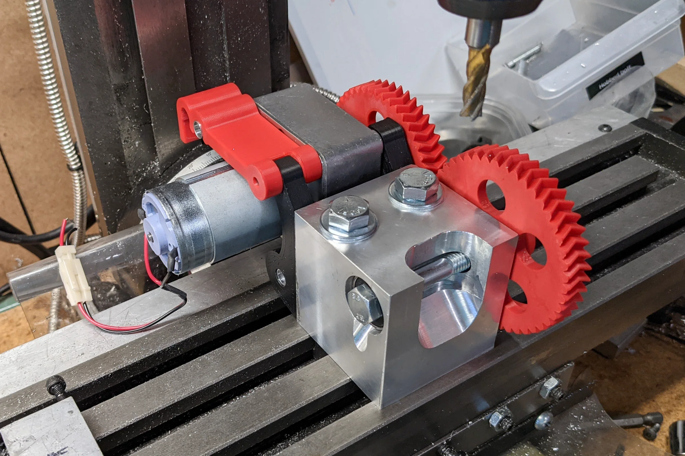
As volume increased, I redesigned the jig with an integrated geared motor to rotate the bolt at consistent speed while the mill cuts the curved profile around the bolt shoulder, then hob the teeth in the same setup without re-fixturing, replacing the handheld drill I had been using to spin the bolt. This is the production jig still in use today.
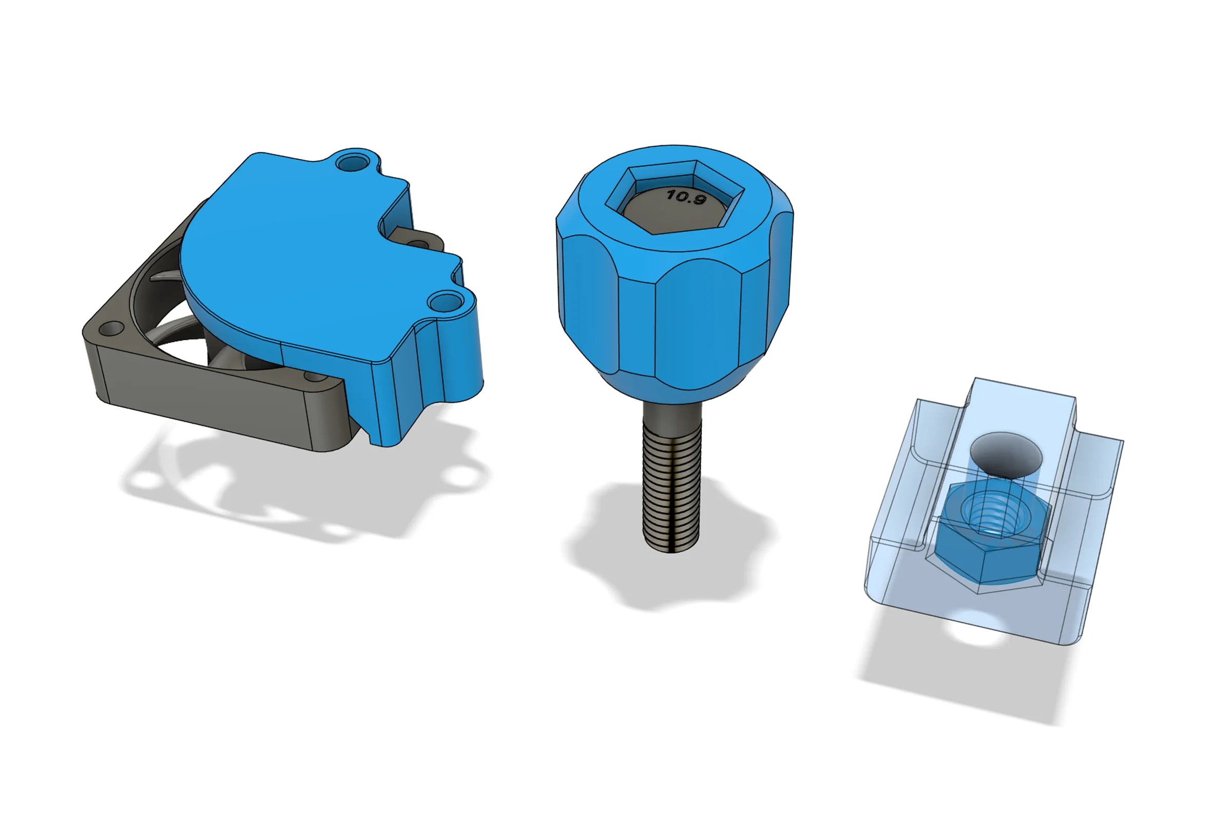
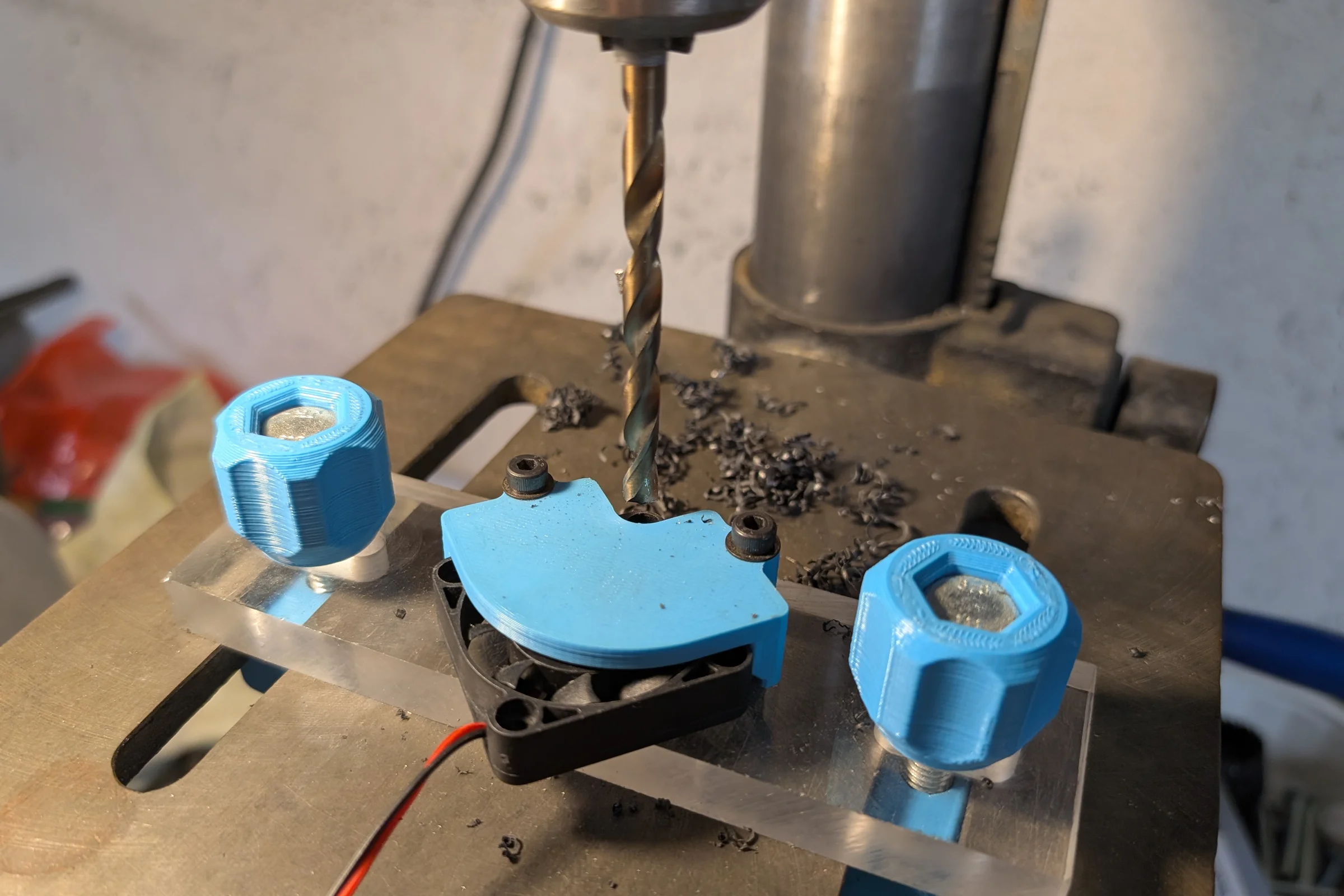
A fourth jig addressed a separate production step: drilling recessed pockets for fan mounting screw heads. Sourcing a more cost-effective fan required drilling new mounting holes into the printhead body. I designed the jig as a combination of off-the-shelf bolts and nuts threaded into a machined acrylic plate, allowing fans to snapping into accurate repeateable position and held under tension without tools for drilling. The jig clamps into the drill press table slot using 3D printed tightening knobs, no tools required. Four custom jigs in total to produce one printhead: two 3D printed, two machined aluminum.
Building the First Printhead: Improvements Along the Way
With the hobbed drive geometry established and the PTFE filament path solved, the first complete 1.75mm printhead could be assembled. The Hexagon hotend I sourced appeared to be from LulzBot's own early small-batch test production. I bought enough to build several validation units and begin field testing.
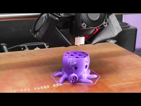
The first validation units went straight into hundreds of hours of continuous torture testing. The most useful test prints were the printhead revision parts themselves — each iteration printing its own replacement components for the next version, stress testing geometry, fit, and thermal behavior simultaneously under real production conditions. Failures pointed directly at what needed to change. The design converged quickly because the feedback loop had no slack in it.
The Fan Electronics Problem
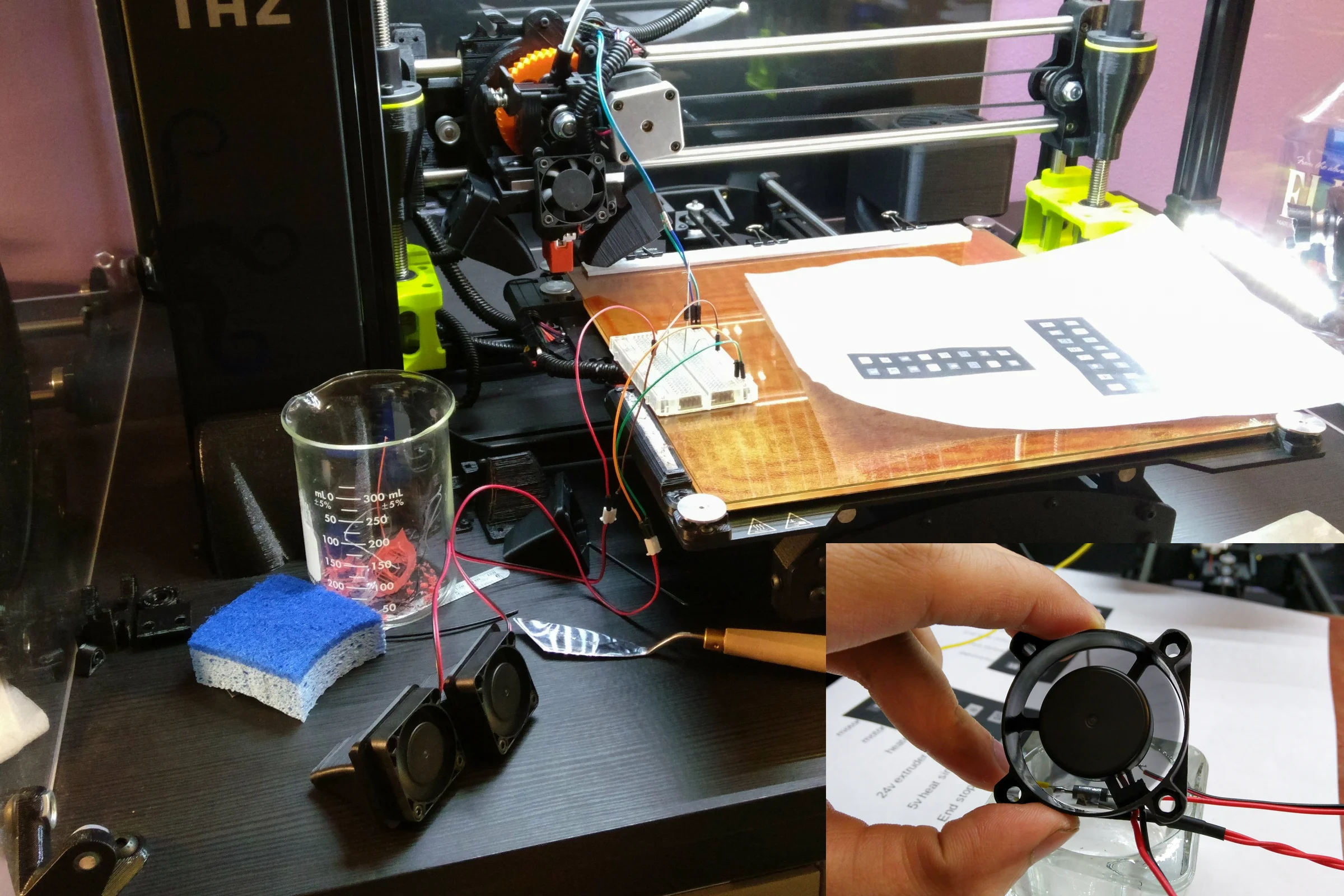
The original printer used 24V fans driven by a 24V PWM controller. These OEM fans were high quality but unnecessarily expensive, making the unit cost too high for a viable replacement part. I tested over 20 affordable 24V alternatives, and every one failed to spin at the low PWM settings required for the initial layers. Good first-layer adhesion is non-negotiable, and these cheaper 24V fans simply lacked the low-end torque to start up at low duty cycles.
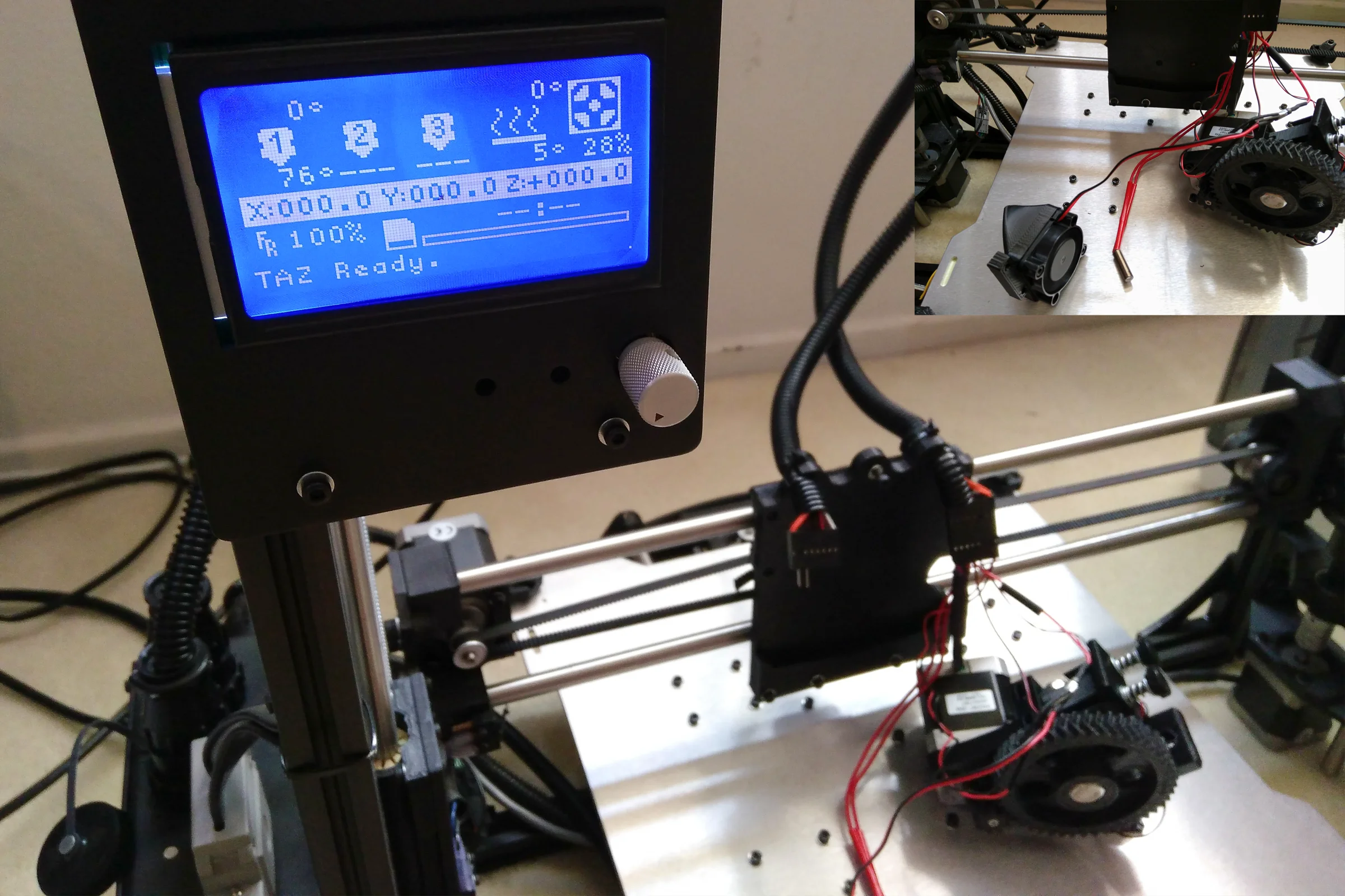
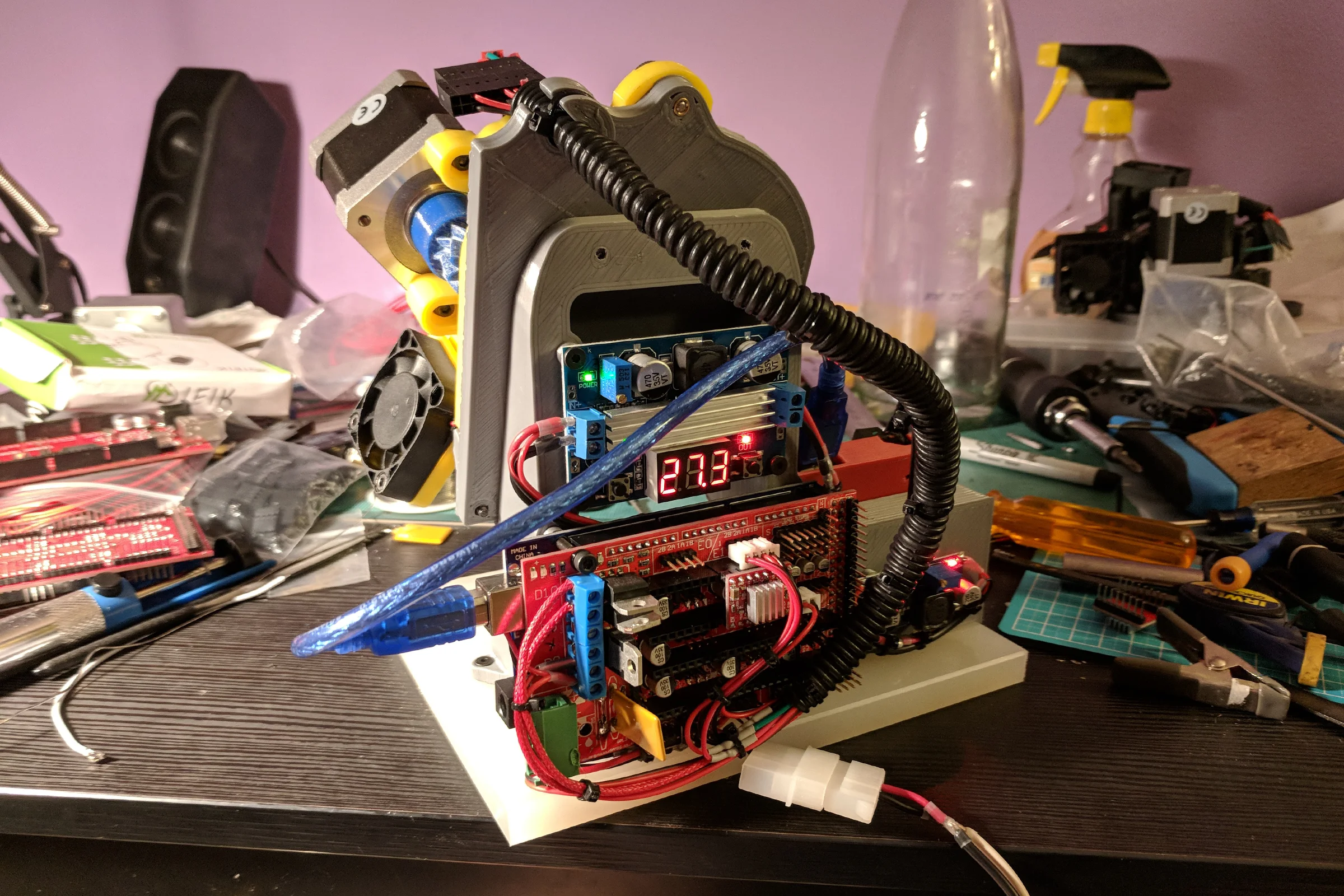
I used a spare printer as test rig running modified G-code to experiment different electrical configurations throughout the entire speed range. I discovered that standard 12V fans responded perfectly across the entire PWM range if the 24V signal was stepped down. The challenge was implementation. Dedicated step-down converters added high cost to my BOM and there was no good space on the printhead to mount one.
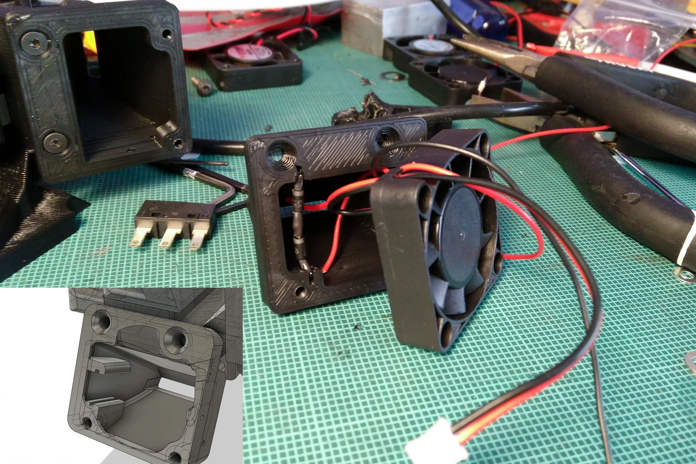
The solution was picking an appropriate diode wired in series with the fan supply to drop the 24V potential into the 12V operating range. This was a simple, low-cost fix that made sense for the application. However, the diode generated considerable heat during operation. Rather than treating that as a thermal problem to manage separately, I redesigned the fan duct in CAD to position the diode directly in the fan's own airpath. This created a self-contained thermal management system where the fan actively cools the diode that enables it to operate reliably.
V2: E3D V6 Redesign
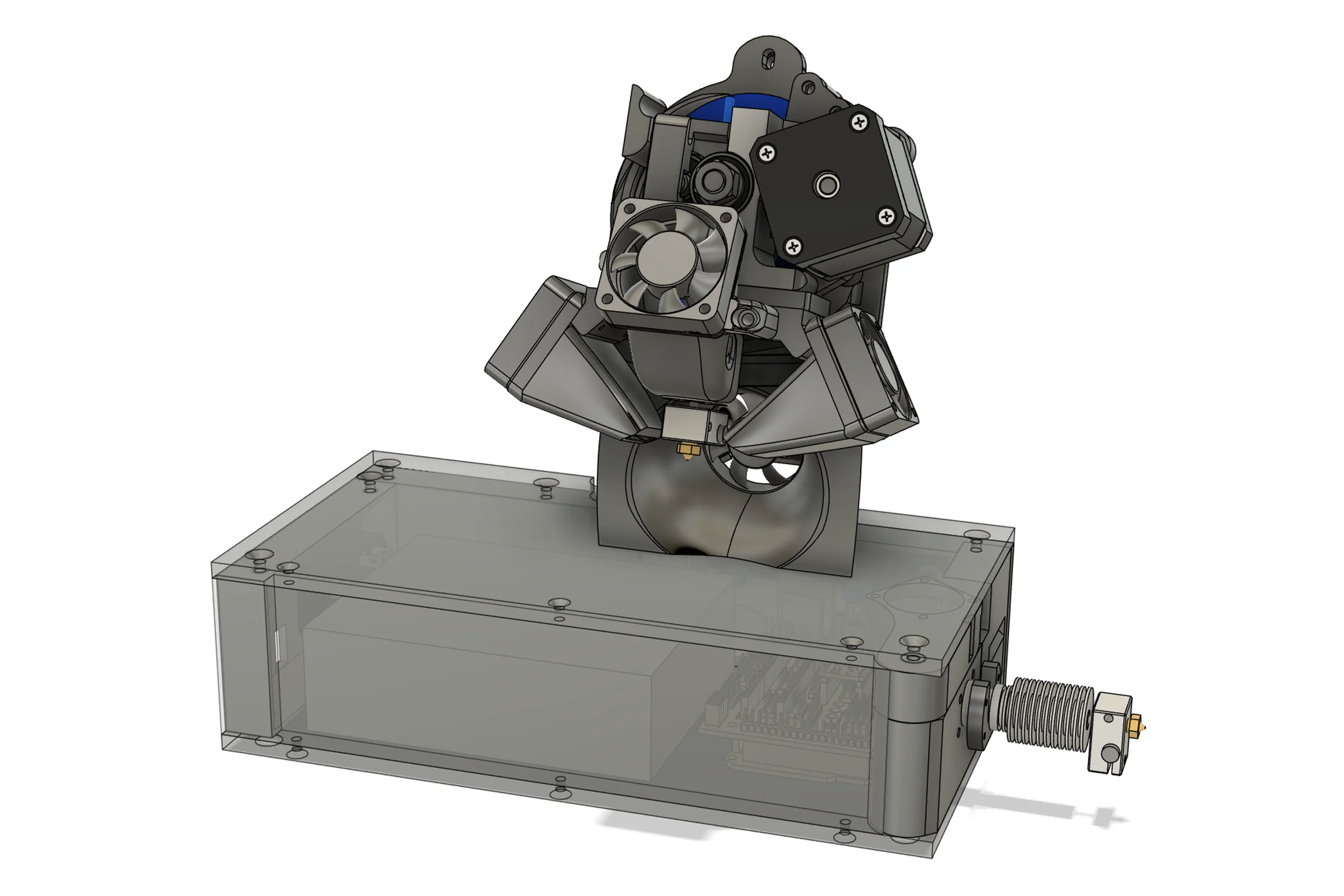
The Hexagon hotend supply eventually ran out. The E3D V6 was the natural successor because of its availability and superior performance, but it was significantly longer than the original Hexagon. This physical discrepancy meant every internal component and mounting geometry had to be redesigned from scratch.
The hard constraint from customer feedback was clear. The external appearance was a highly valued selling point and had to remain as close to the original as possible. Customers appreciated the familiarity and the reliability the design provided. I renegotiated every internal component shape and mounting geometry against the V6 dimensions to fit the longer hotend inside the original external footprint. The result was a meaningfully better hotend under the hood with no visible change to the machine and no slicer profile updates required.
The V2 redesign also integrated over 30 discrete improvements collected from V1 field deployments. I used observations from refurbished units returned after thousands of operating hours to identify and eliminate long-term failure modes. Most of these changes were invisible to the user, but they accumulated into a meaningfully more reliable product that was easier to assemble.
Scale, Calibration, and OEM Validation
Alongside the V2 redesign, I built out a complete testing and calibration workflow. Purpose-built calibration stations designed in Fusion360 and 3D printed, each printhead calibrated and validated against a known standard before shipping. The stations carry only the bare minimum hardware required, with firmware configured and compiled to mimic exactly how the TAZ hardware behaves. From the printhead's perspective there is no difference between the calibration station and the actual printer. Custom G-code sequences run full verification cycles and calibrate E-steps to confirm each unit behaves exactly as commanded in the physical world before it leaves. The calibration station went through multiple design iterations to improve throughput and reduce setup time per unit. Every single unit shipped went through this process. Across 2,000+ units sold, not one complaint about print performance was ever received — eBay feedback from customers consistently praised print quality specifically.
V2 expanded into three SKUs covering different LulzBot printer configurations, all produced on the same additive workflow. Many customers operated large print farms and kept redundant printheads to minimize downtime. Some shipped units back regularly for refurbishment. Seeing production printheads after thousands of hours of actual use drove the continuous small revision cycle that ran throughout the product's lifetime.
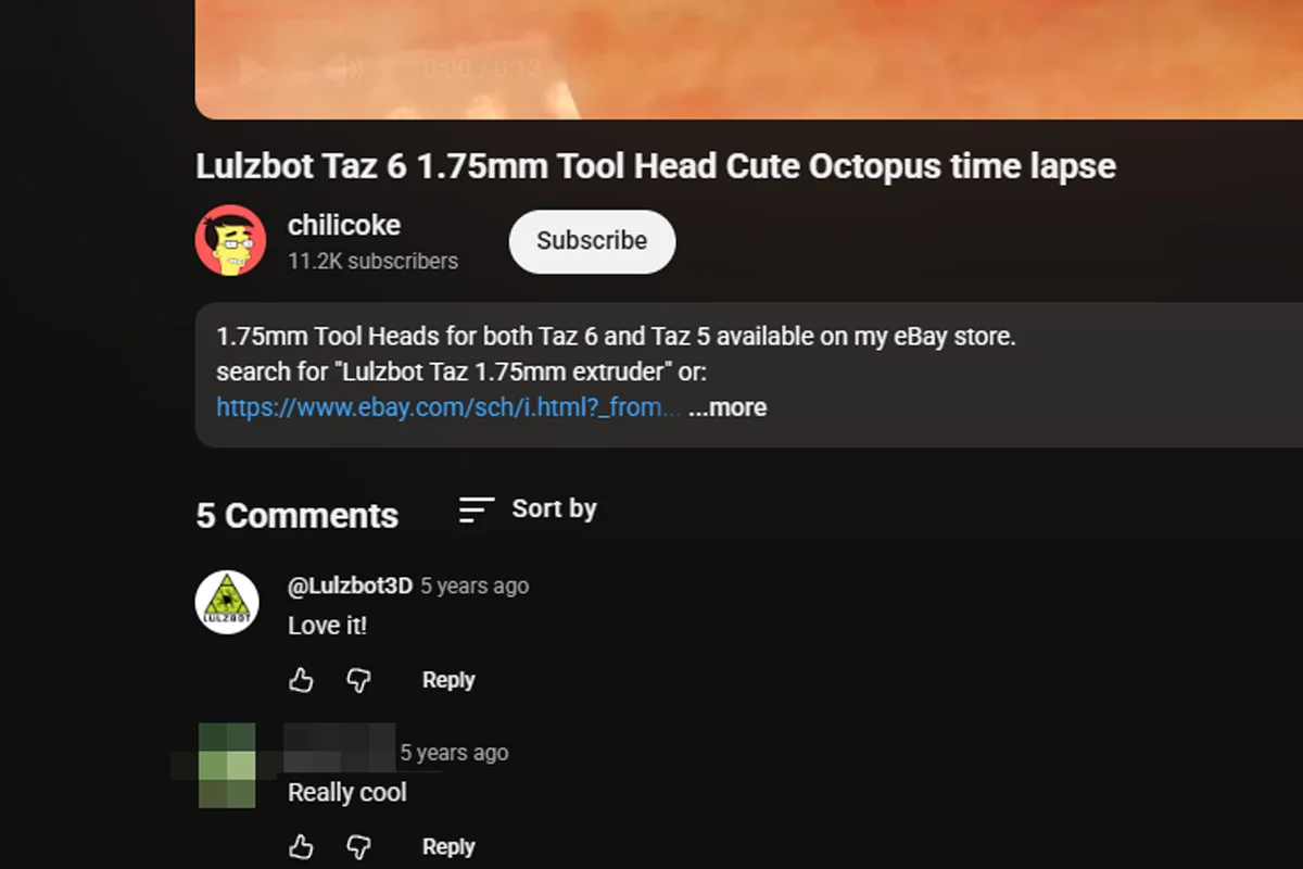
LulzBot's internal engineering team privately reached out and publicly commented on my YouTube channel commending the work. When LulzBot later released their own official 1.75mm printhead, customers who tried both often reported preferring the simpler, original-style architecture: more reliable, easier to unjam, and significantly easier to service.