The Mill
Trilogy
Two used X2 mini mills, one used to machine the modifications for the other, building a precision super mill with miniaturized internal DRO electronics, ball screws, and a custom power feed designed from scratch. Then a third higher-quality mill from Little Machine Shop converted to full 3-axis CNC: every component designed in SolidWorks, machined from 6061 aluminum on the super mill, and integrated with Geckodrive motion control with no kit hardware.
Mills #1 and #2: Building a Better Machine
X2 mini mills were the only desktop-size machines available to hobbyists at the time, known to be fairly subpar out of the factory. CNC conversion kits existed but together with the mill would run well into the $3,000 range. Buying two used machines for next to nothing made sense. They usually came with tooling from previous owners worth significantly more than the asking price. One happened to come with ball screws and digital scales already, which turned out to be a significant cost saving for what came next.
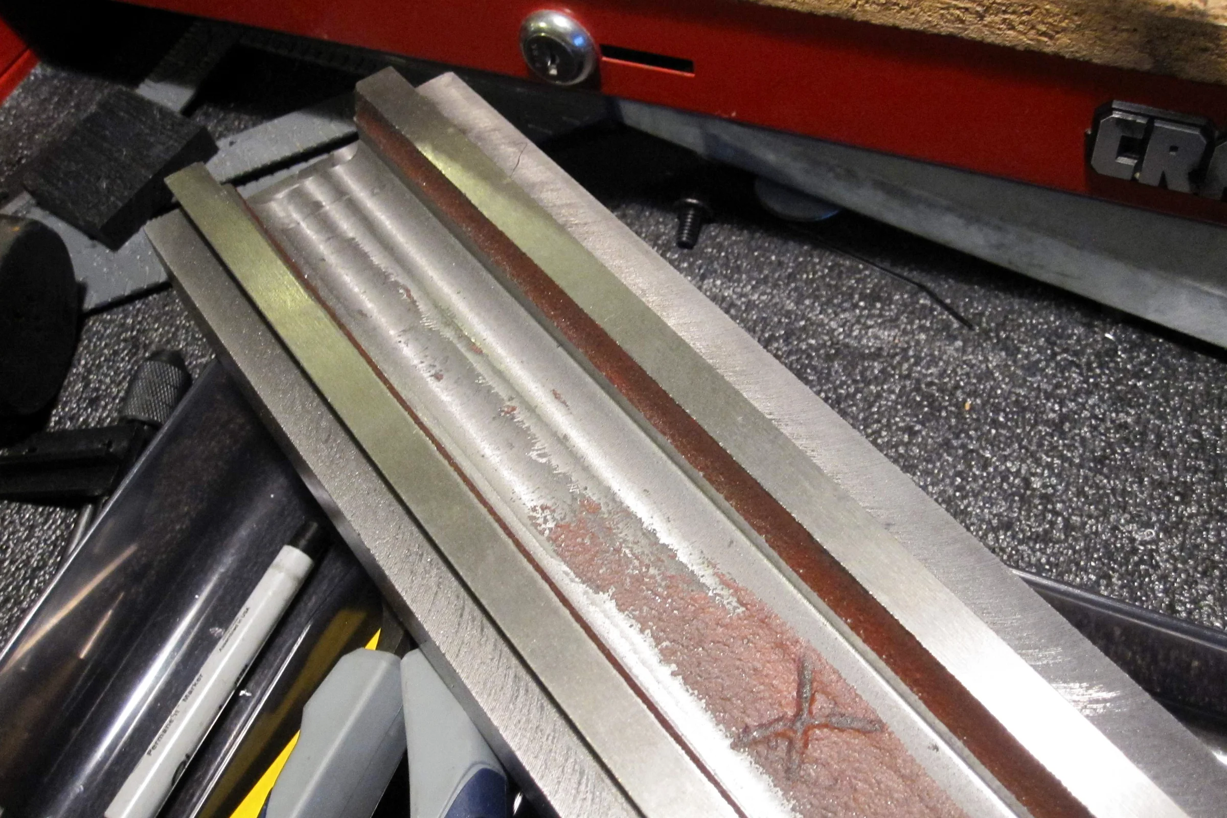
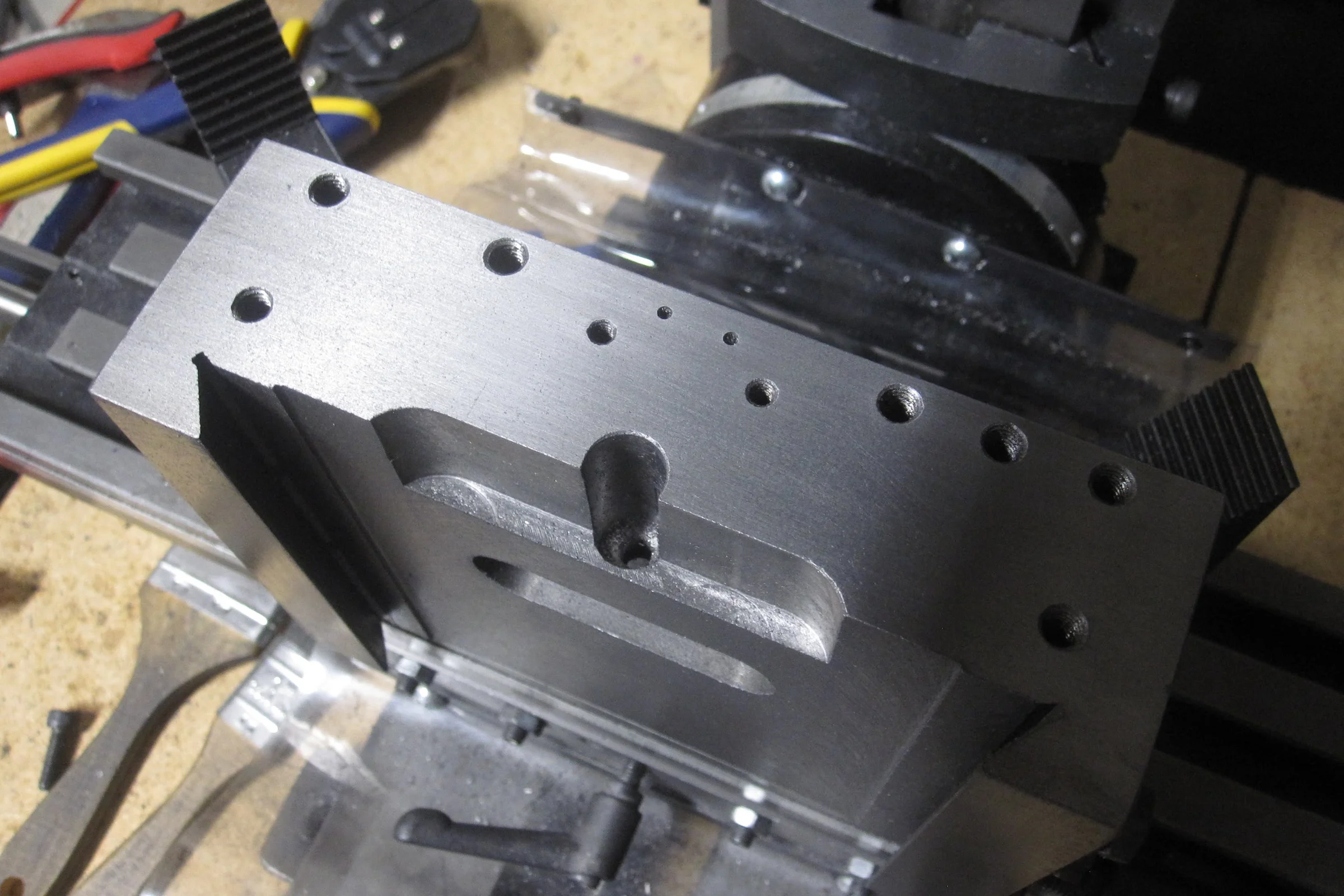
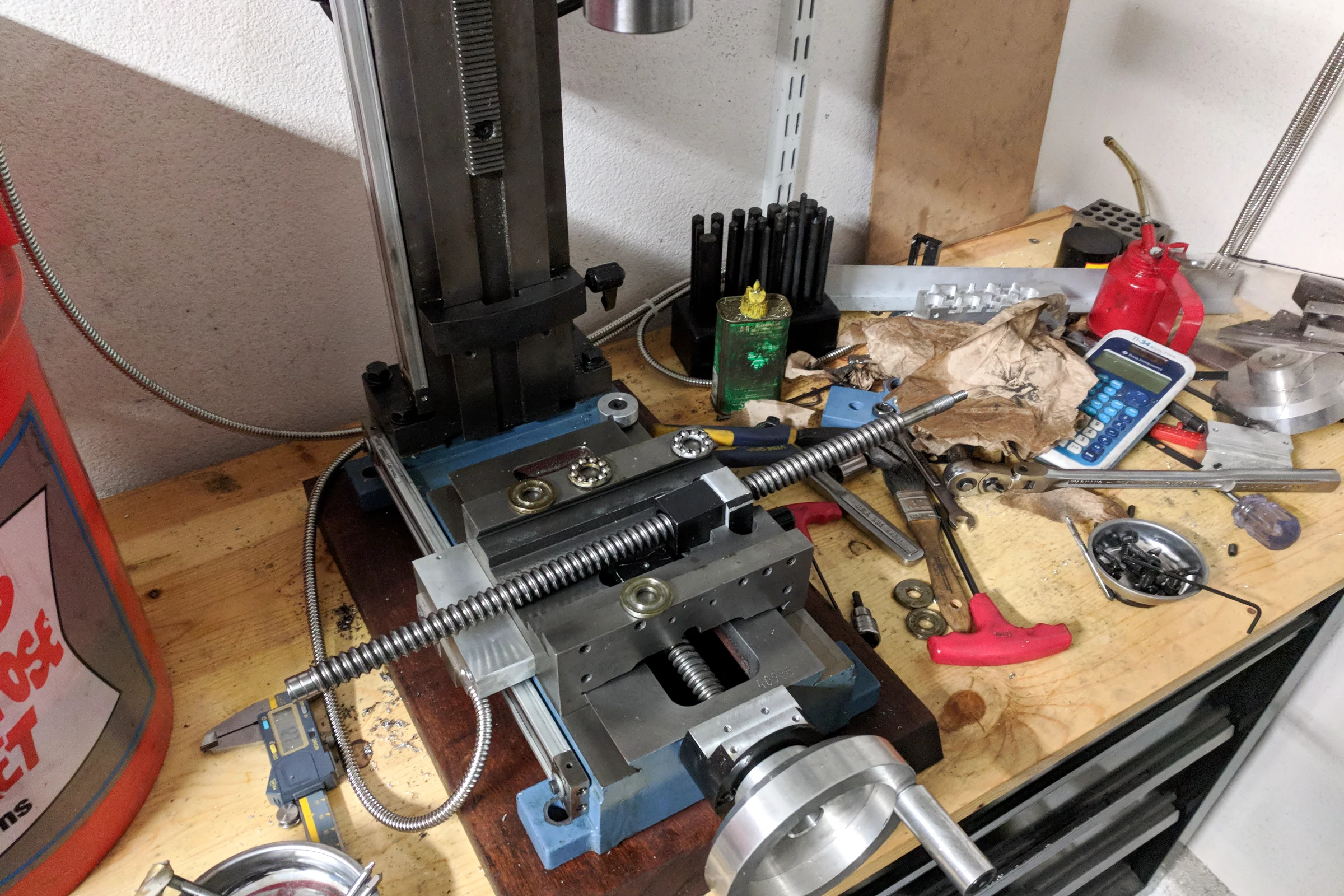
One mill was used to machine the modifications for the other. Full teardown first: blueprinted all axes, compound-ground and polished the dovetail ways to remove factory tool marks and establish true reference surfaces. Chinese import castings are functional but their surface finish and geometric accuracy leave significant room for improvement. Replacing bushings with ball bearings followed. The goal was a machine accurate and repeatable enough to produce CNC-grade components on its own output.
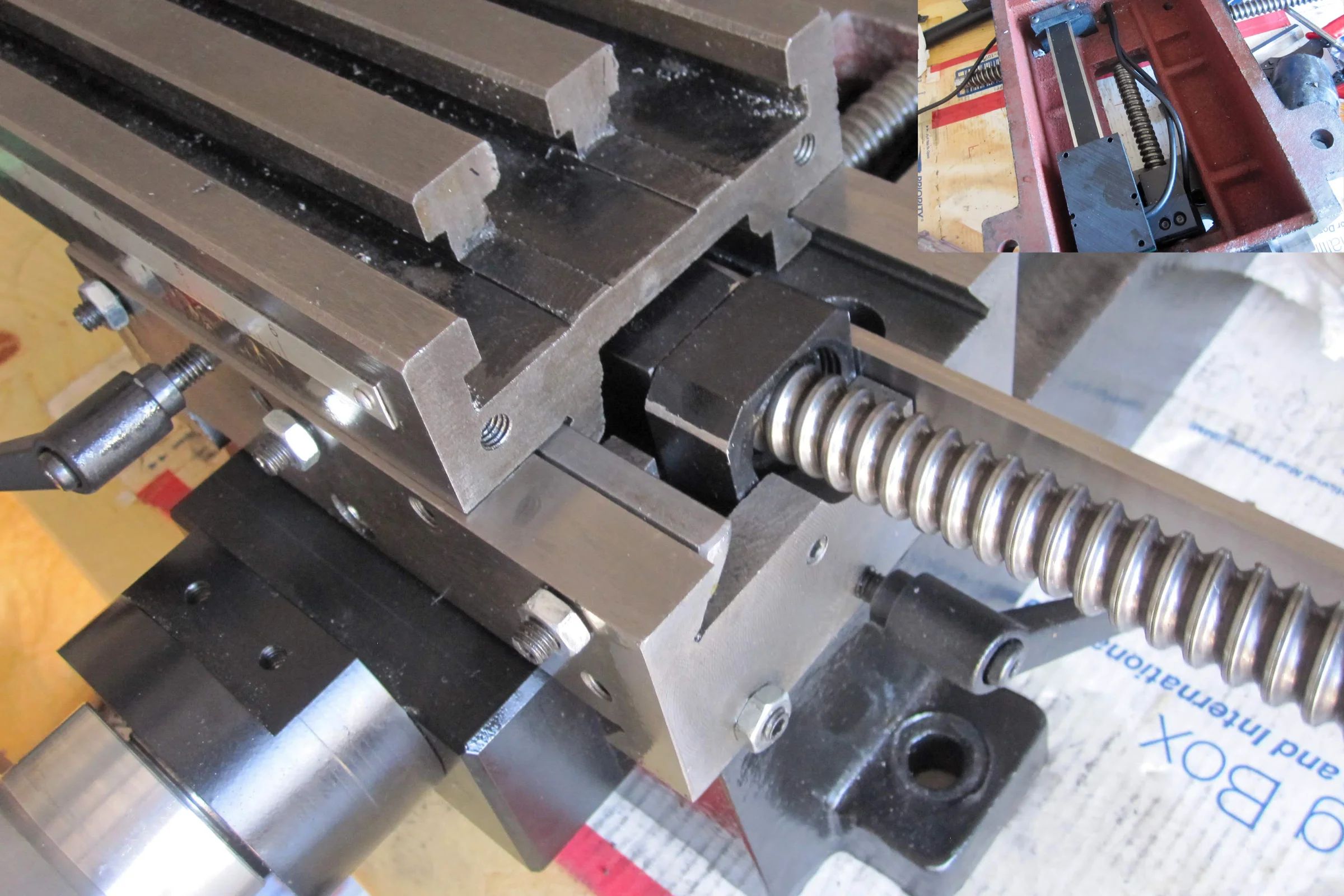
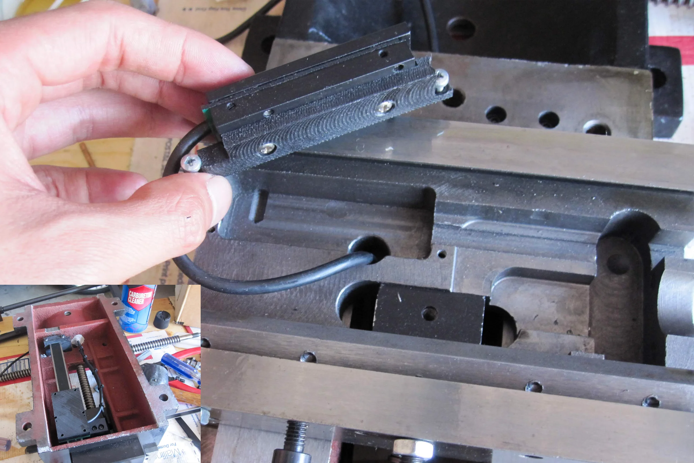
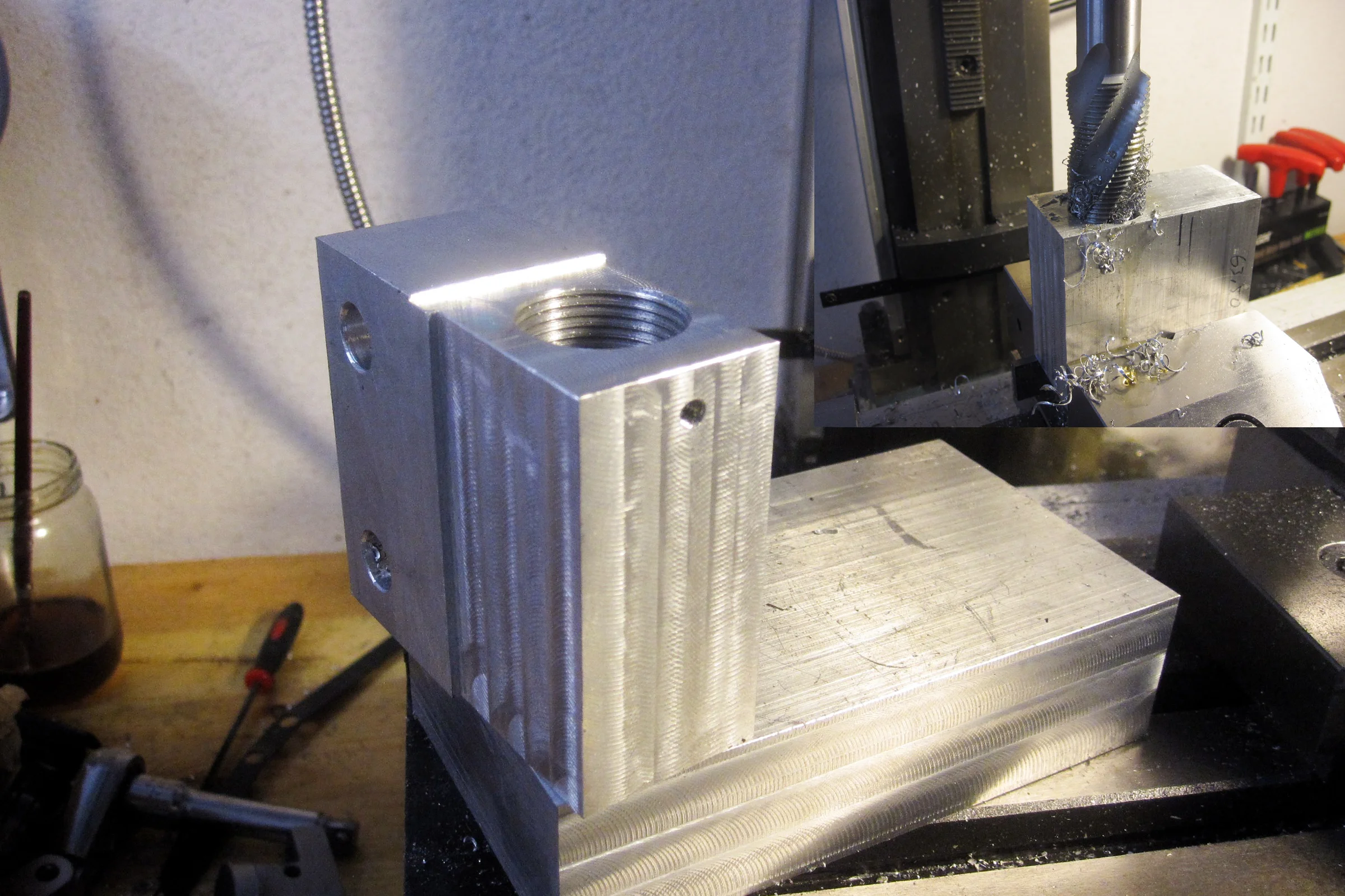
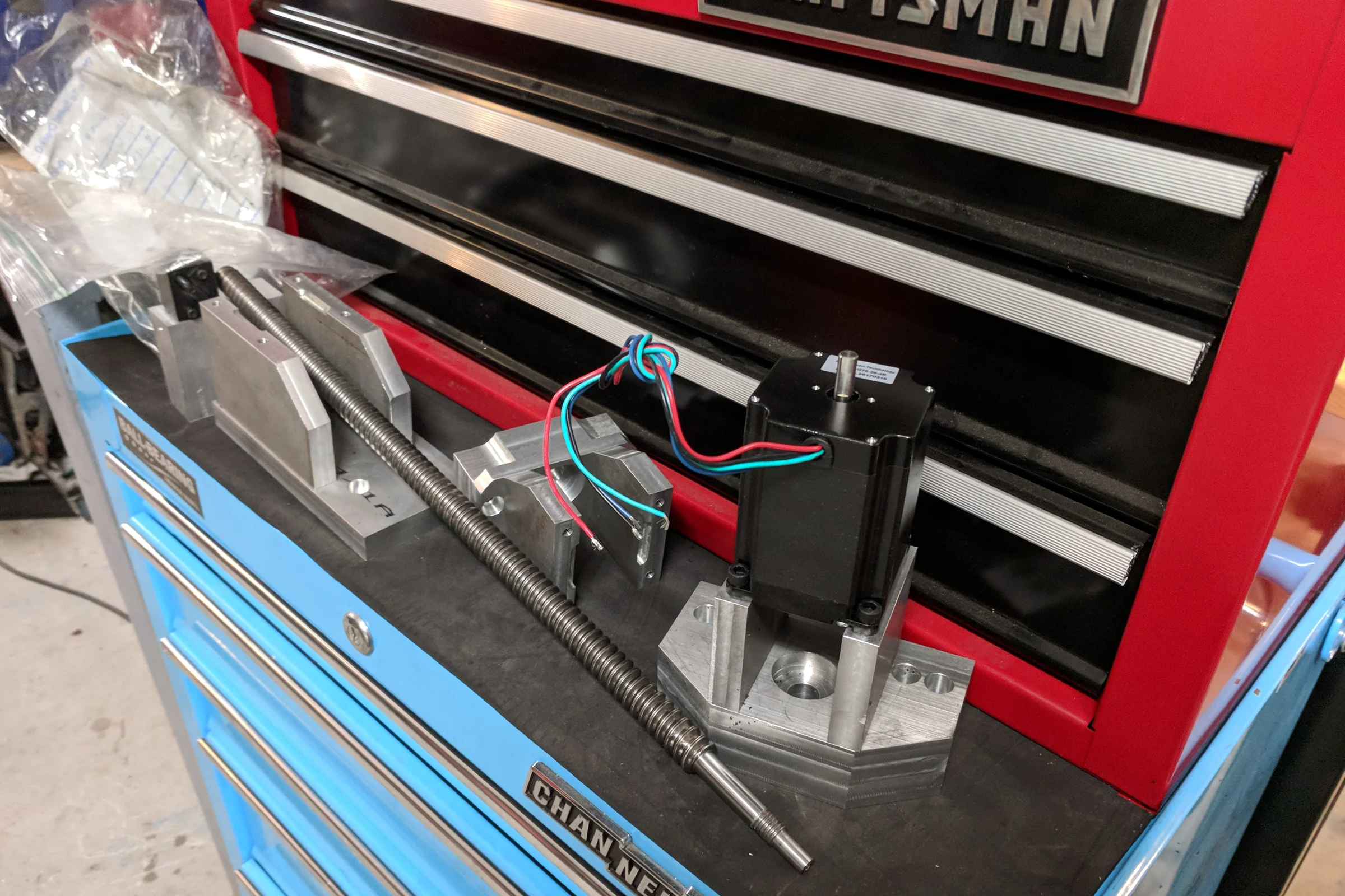
The ball screws themselves transferred across all three axes. The previous conversion hardware was hacked together and unusable, so all the conversion components were redesigned and remilled from scratch, in addition to milling the necessary clearance into the underside of the table ways to accommodate them. The digital scales followed, long linear encoders that output the same signal as digital calipers.
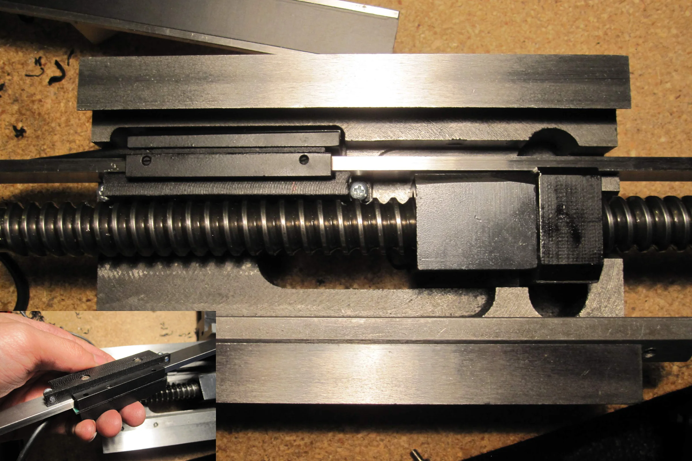
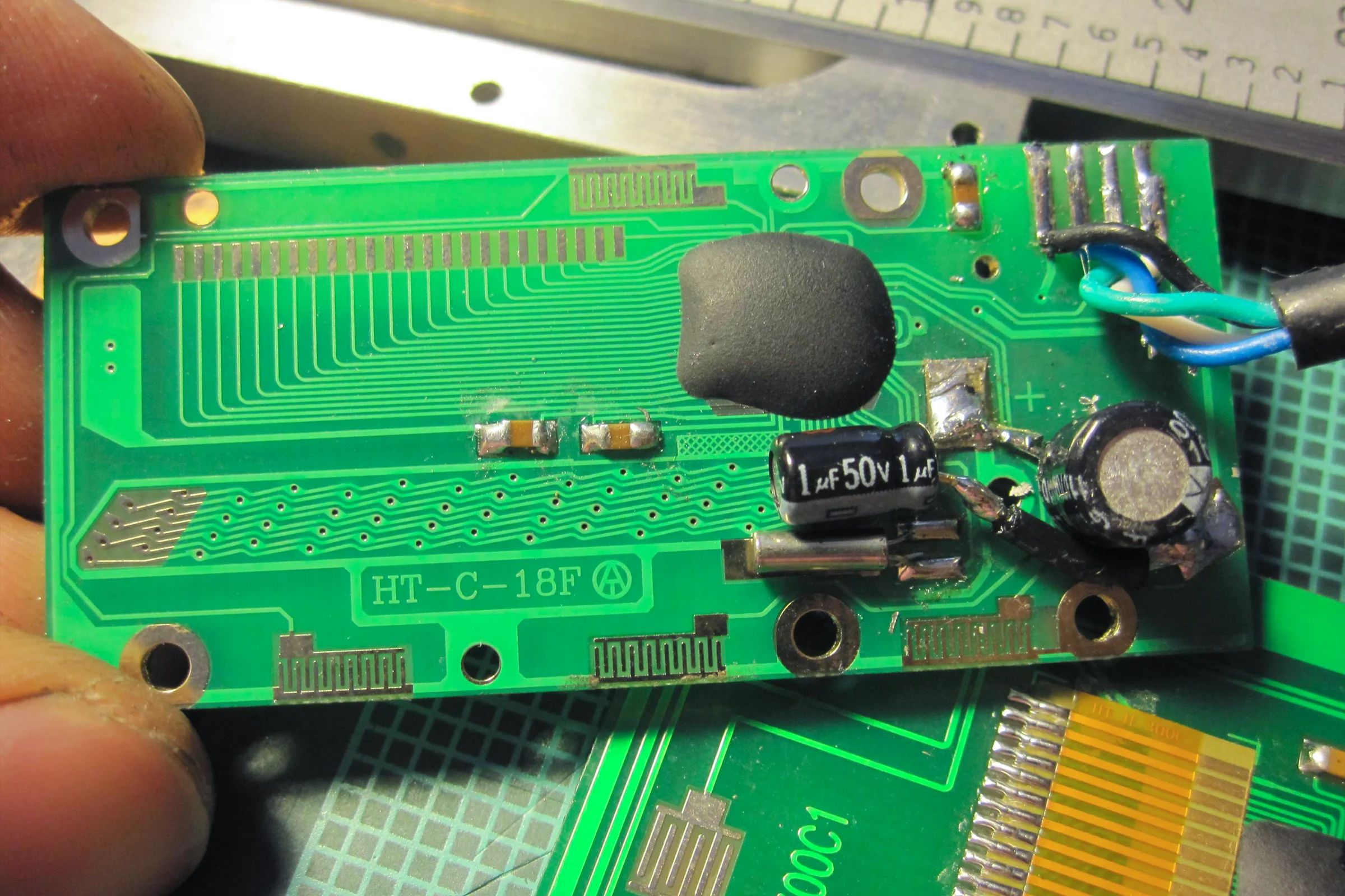
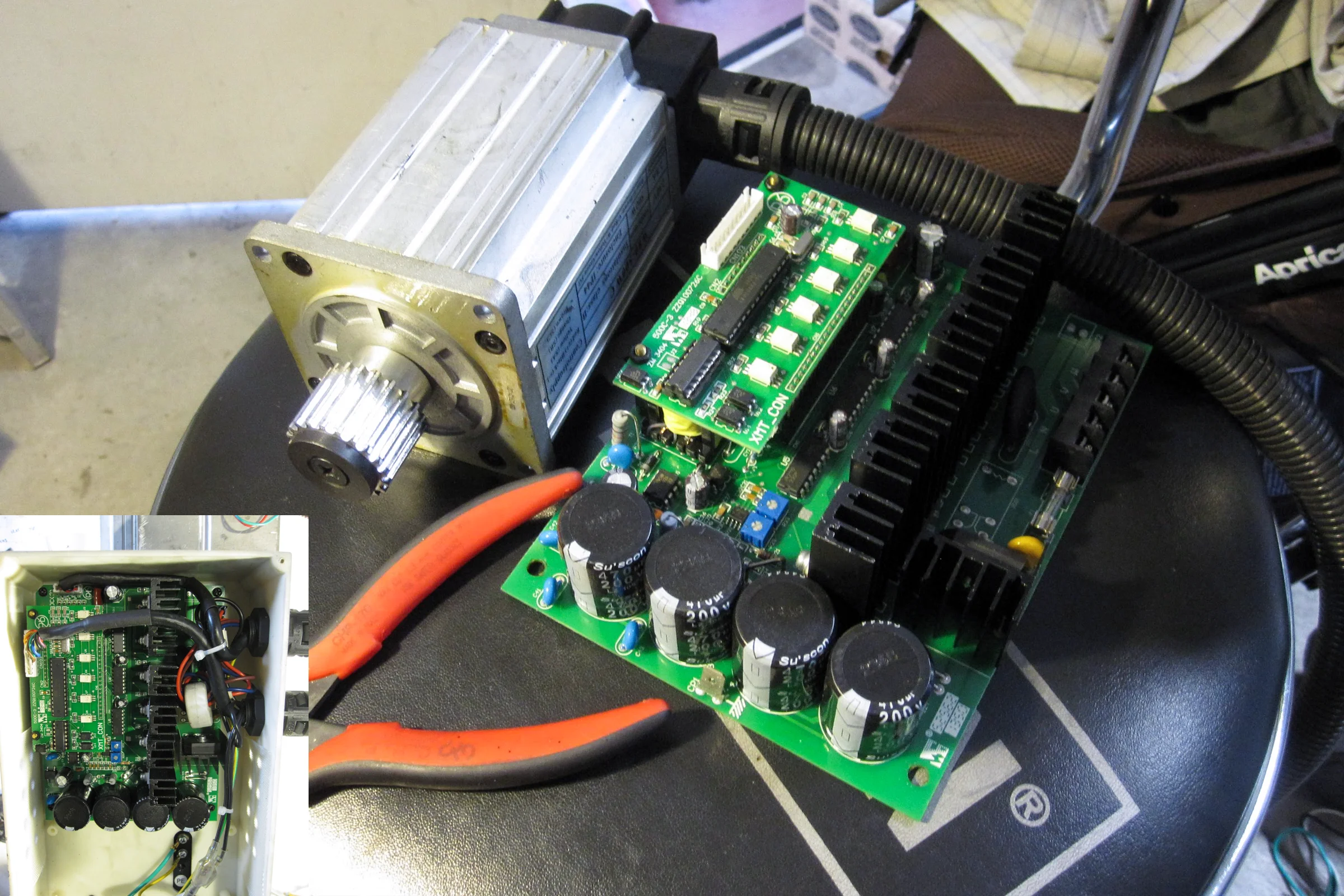
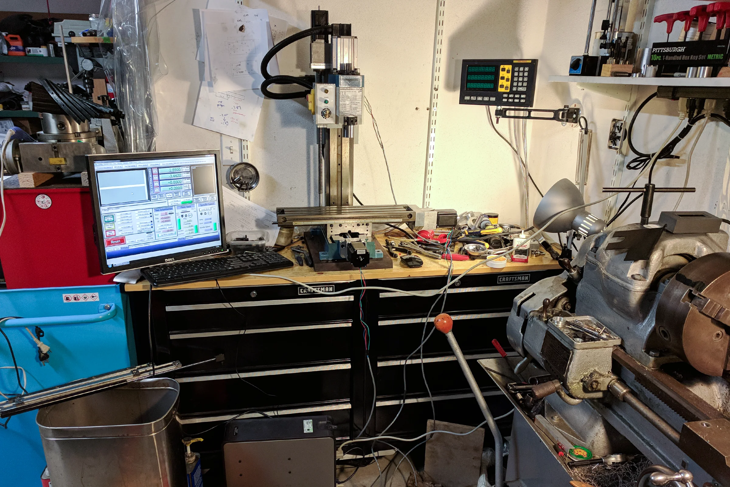
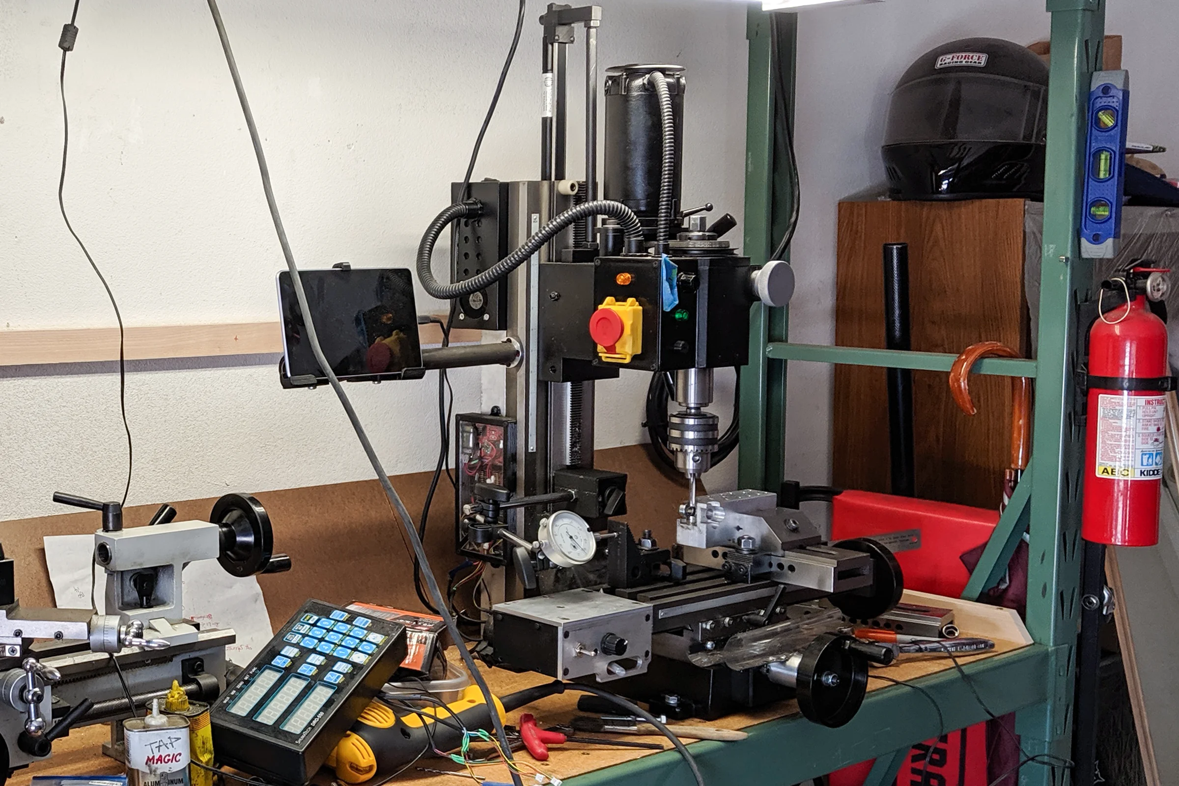
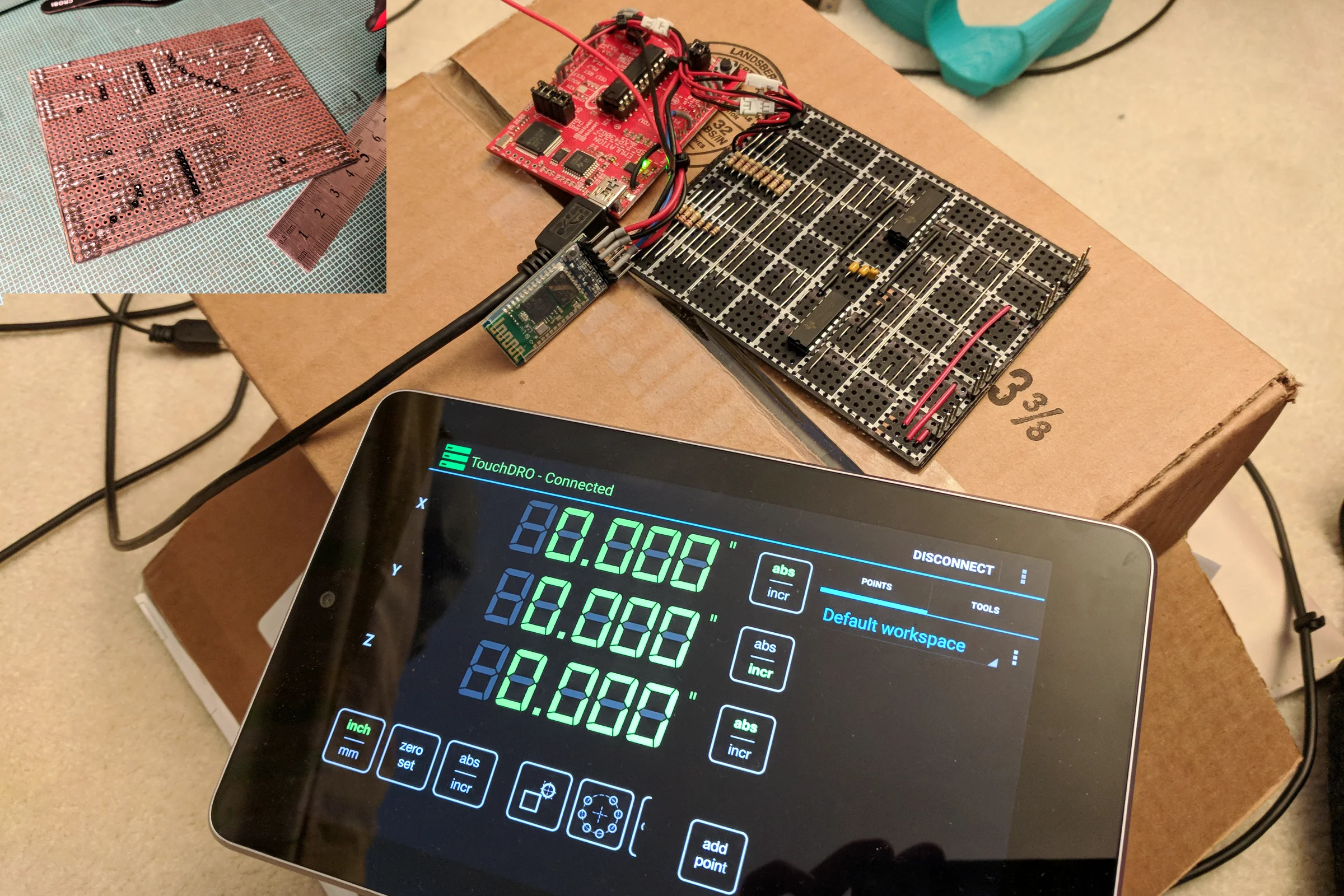
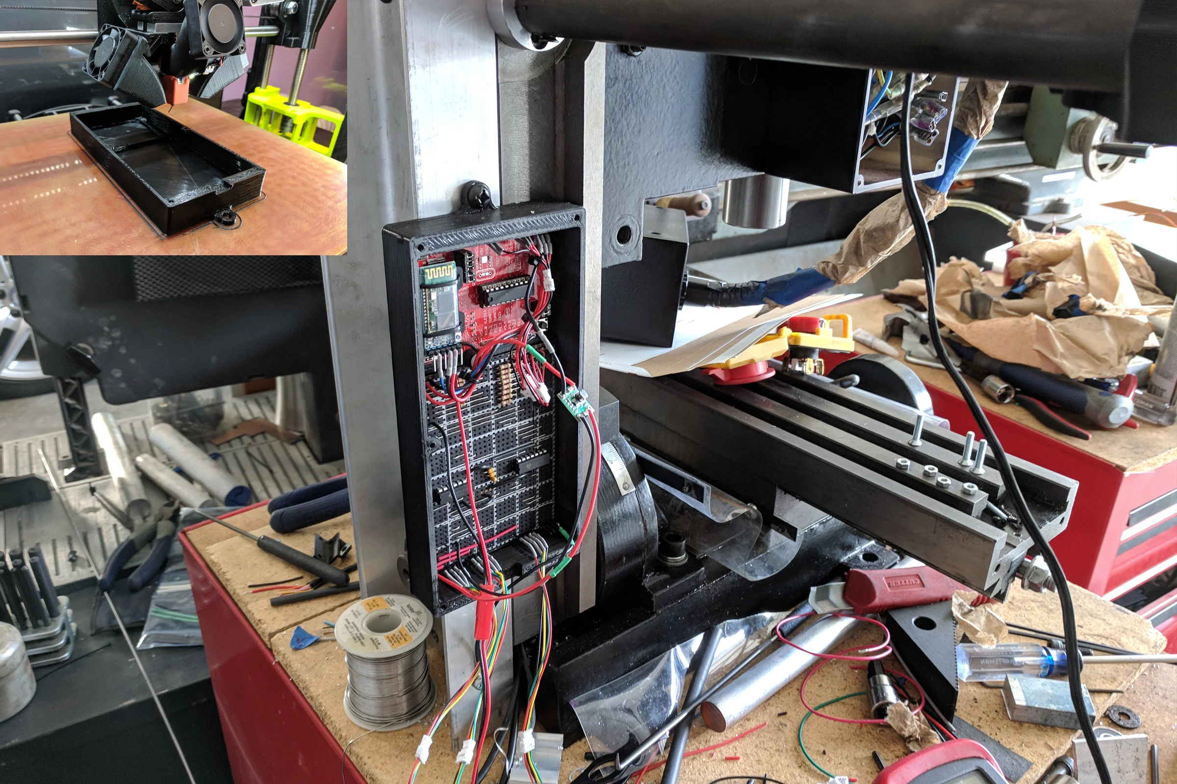
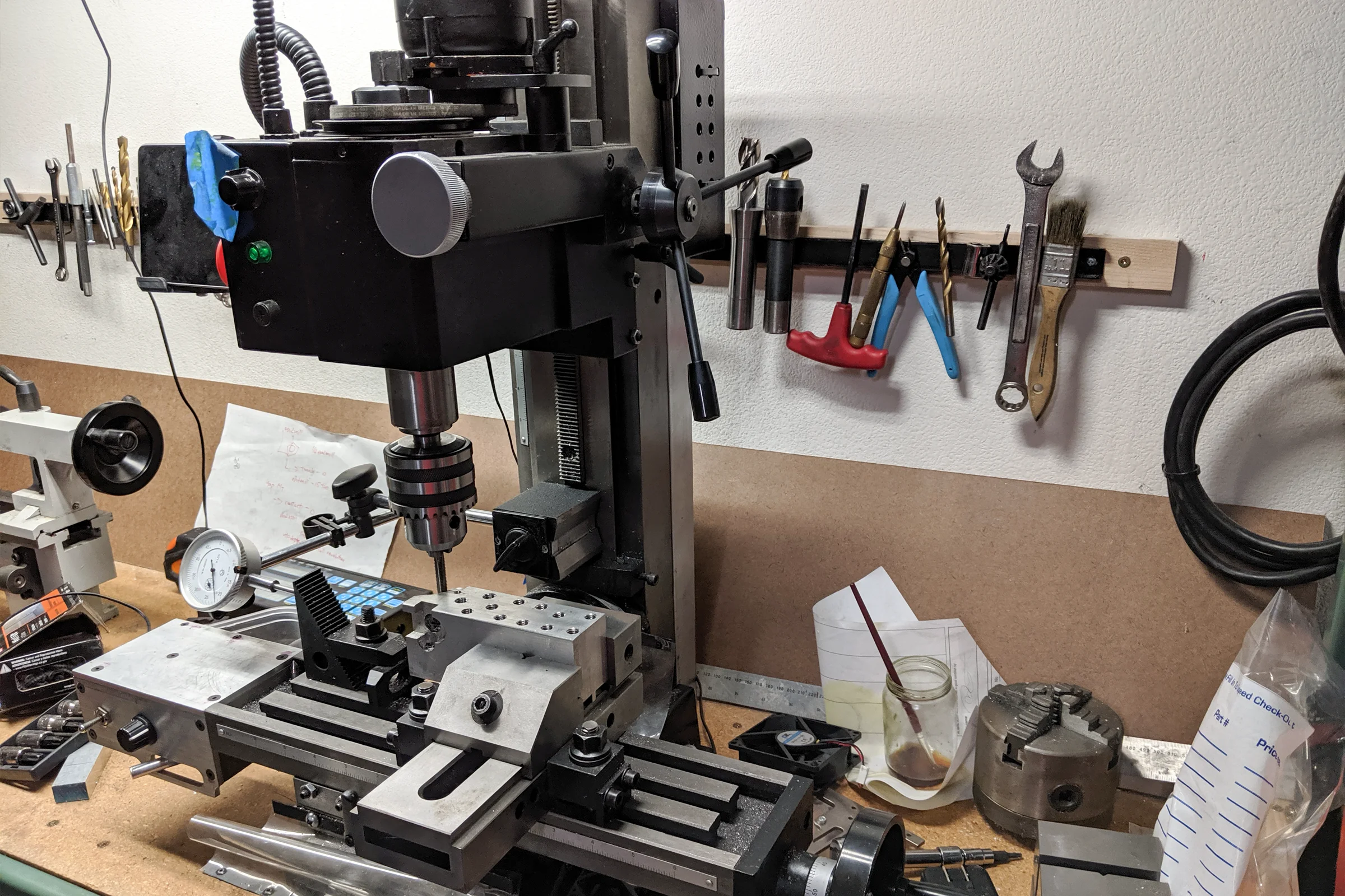
The DRO integration was the part most hobbyists take shortcuts on. The typical approach mounts scales externally with brackets hanging off the outside. Functional enough, but it adds stack-up, creates snag points, and looks bolted on as an afterthought. Instead, I stripped the digital caliper circuit boards down to their minimum, removing the LCD, buttons, and every unnecessary component, then designed and milled custom aluminum enclosures in CAD sized to fit inside the milling table alongside the ball screws. Everything internal, nothing hanging off the outside. An open-source interface circuit built on a breadboard connects the scales to an Android tablet as a full three-axis DRO display. Custom 3D-printed enclosure for the interface board, mounted cleanly on the side of the mill.
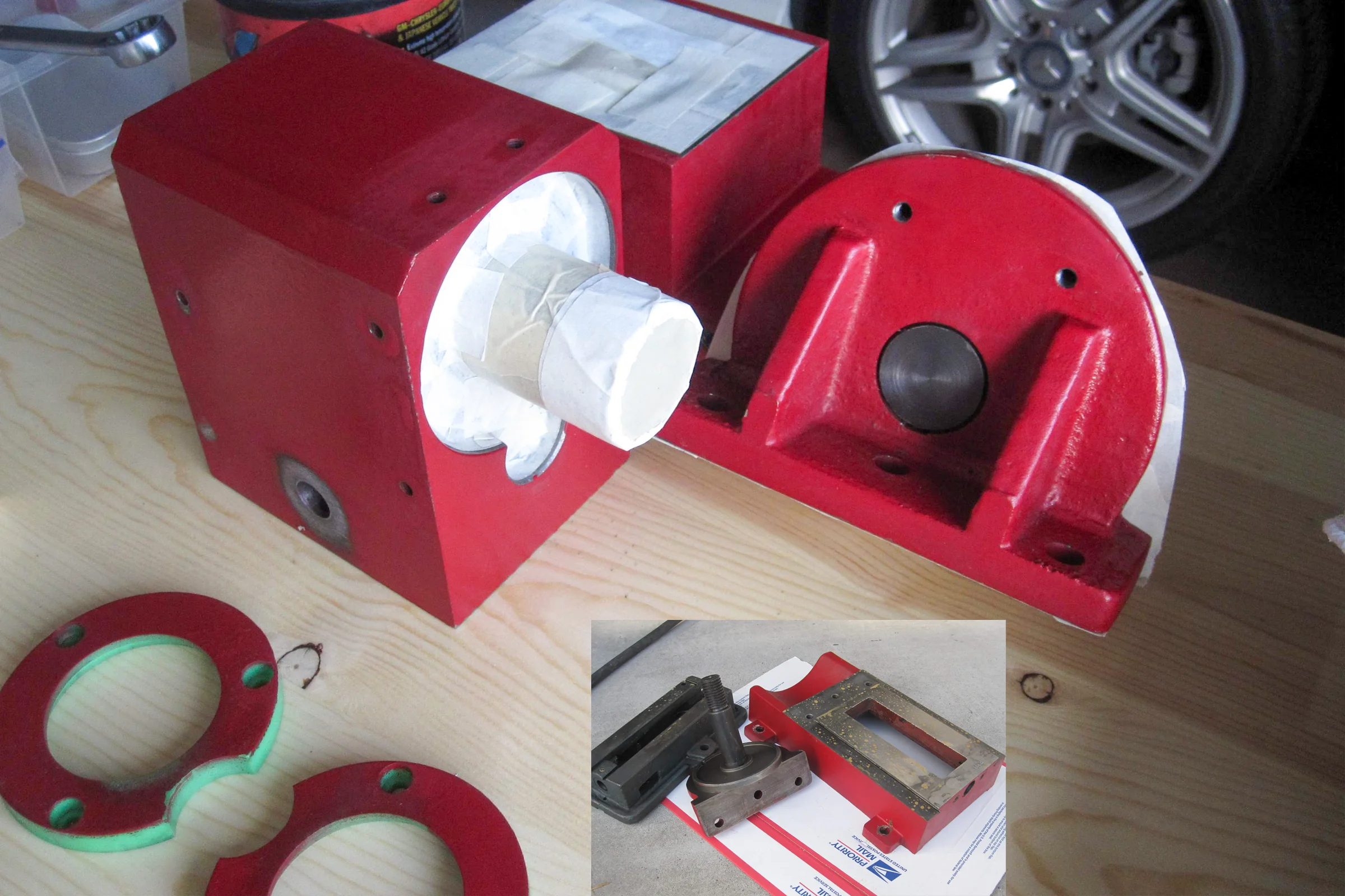
Powder coated all the bare aluminum and cast iron components flat black. Seals the surface, makes cleanup faster, and makes the machine read as a designed unit rather than an assembled collection of parts.
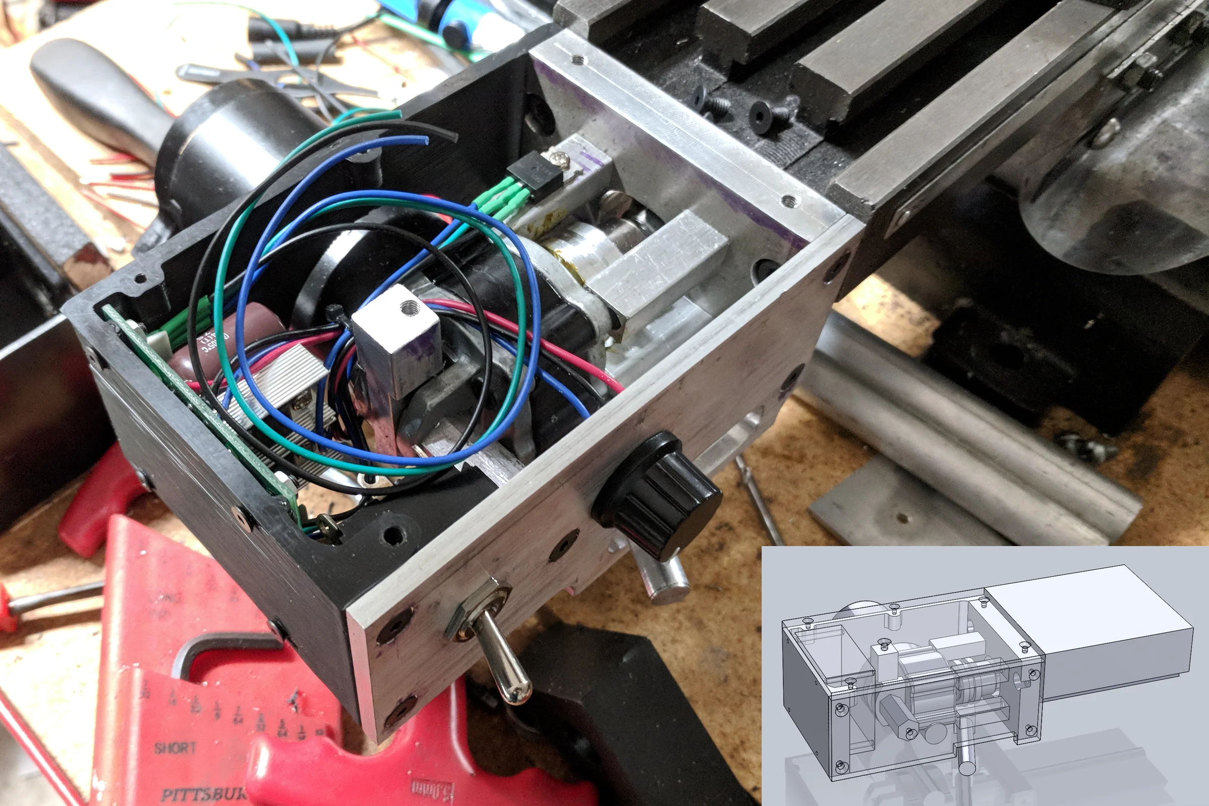
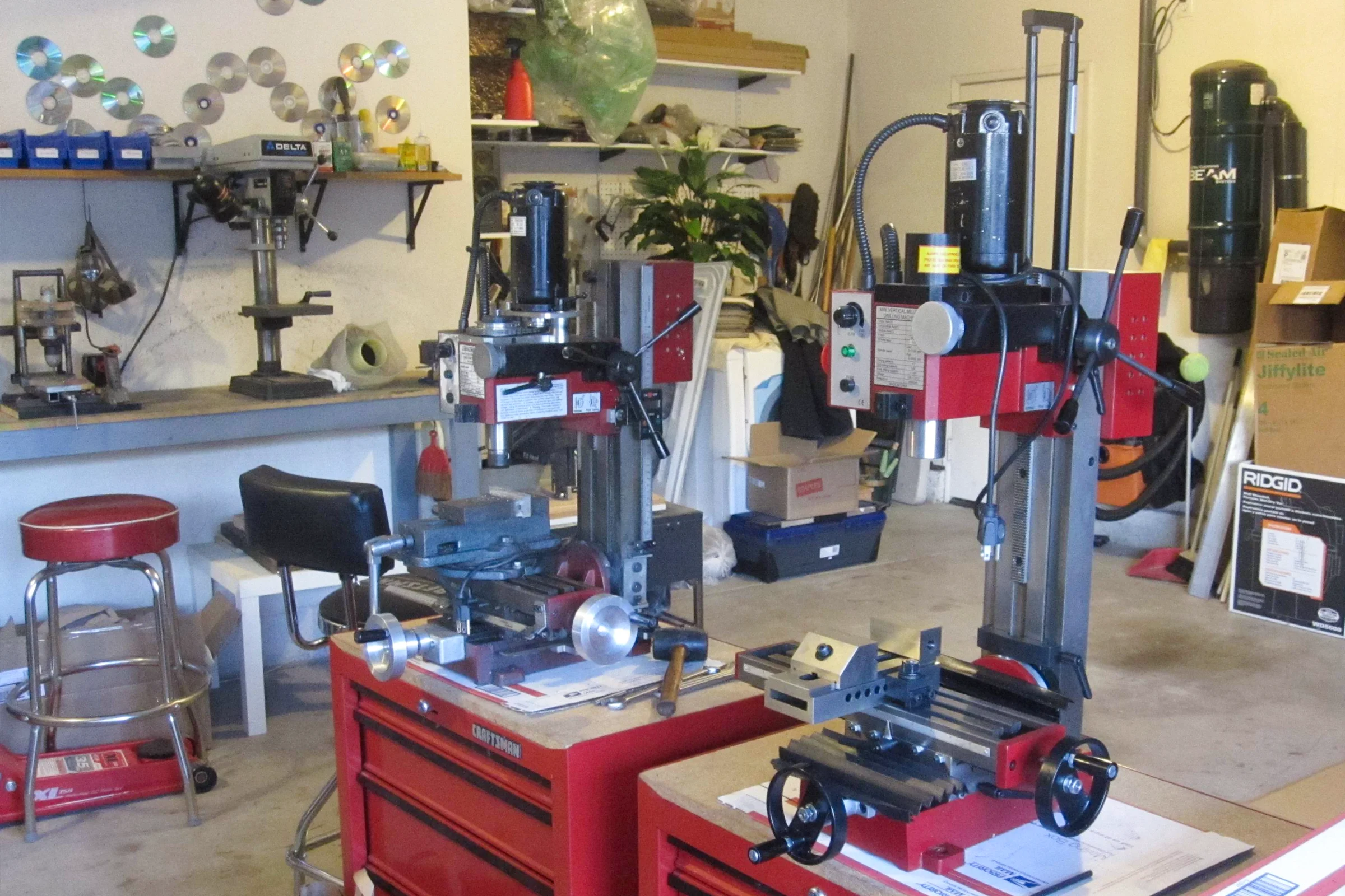
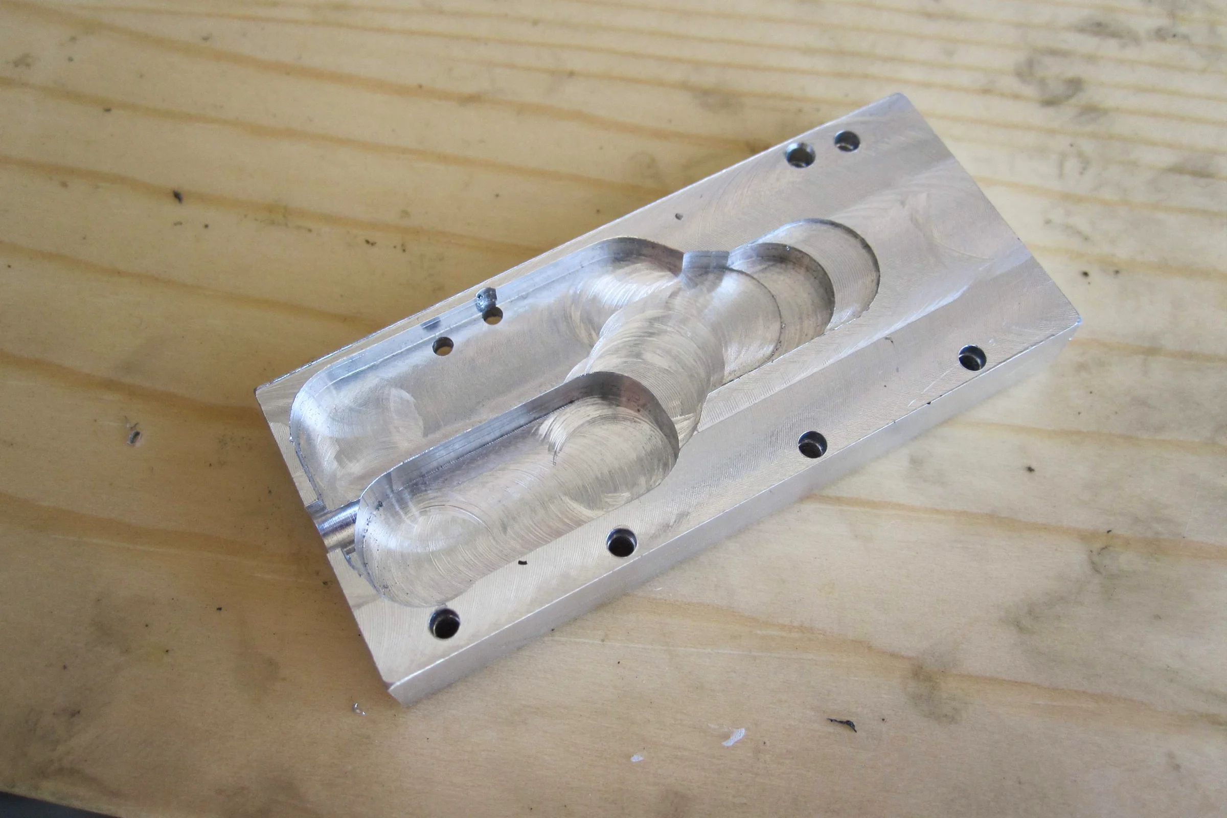
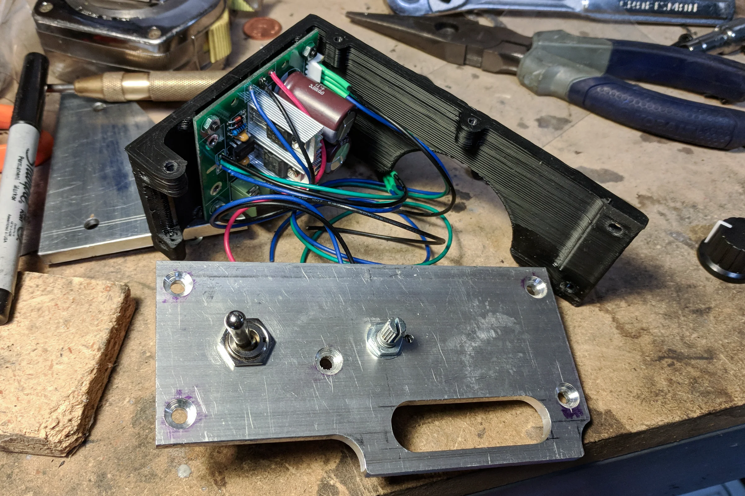
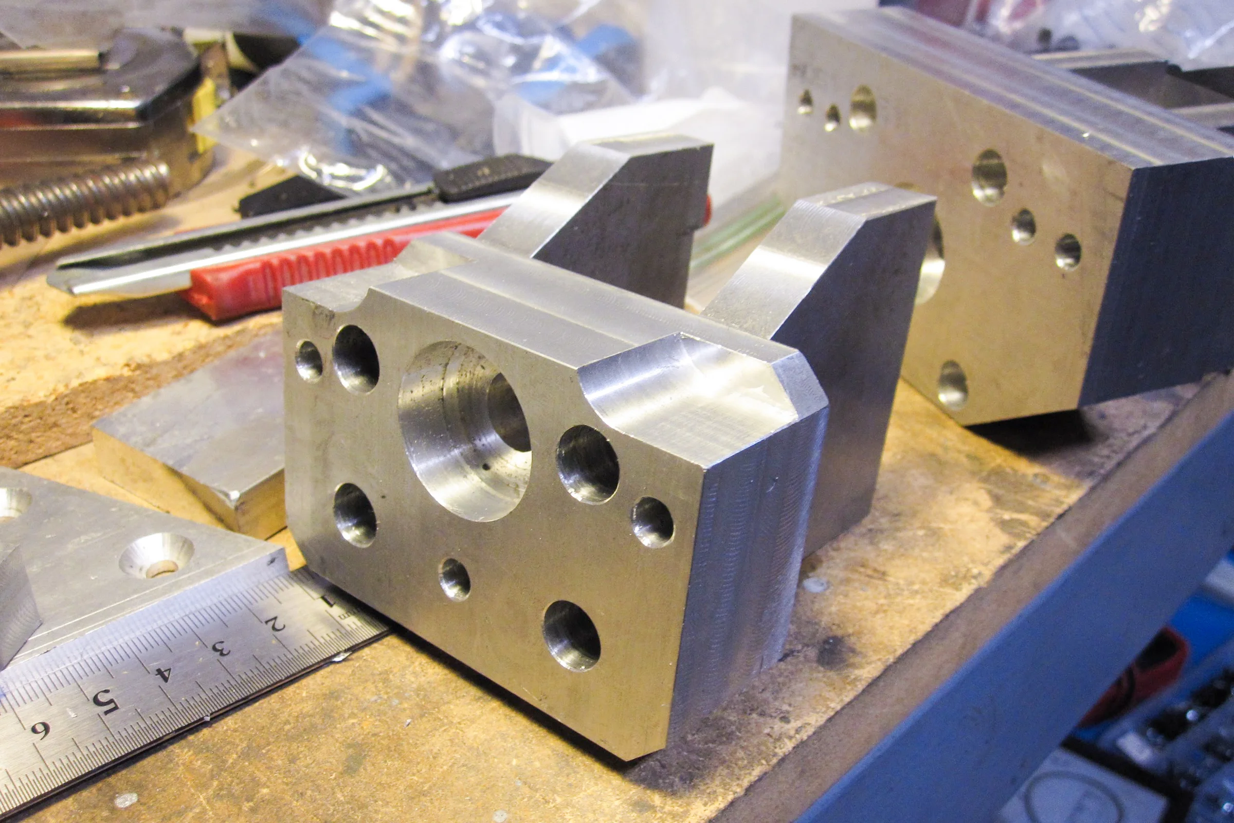
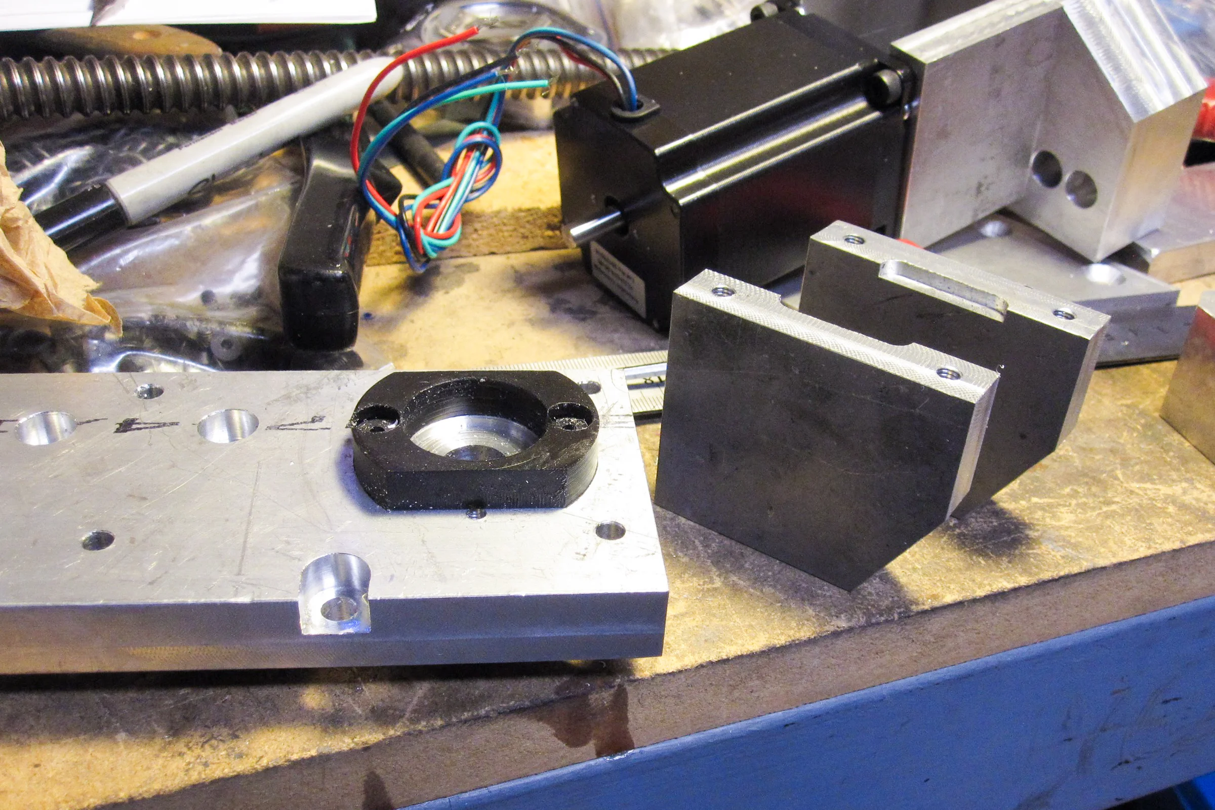
The last thing the super mill needed was a power feed. Commercial units existed but were bulky and expensive. The requirement was straightforward: a motor with speed and direction control, coupled to the X-axis ball screw. A car window regulator motor from Amazon with a 90-degree reduction gearbox built in, combined with a bidirectional speed controller from AliExpress. Measured everything with digital calipers, modeled the full design in SolidWorks, bought 6061 aluminum stock from a local metal supplier, and had a working power feed the next day. The finished unit is one-third the footprint of the commercial equivalent, designed with integrated access panels for the motor controller and speed potentiometer from the start rather than added as an afterthought. Quick-disconnect using standard 3/8" socket drive components. Sitting next to a commercial power feed, it looks like the commercial unit is the afterthought.
Mill #3: Designing the CNC Conversion
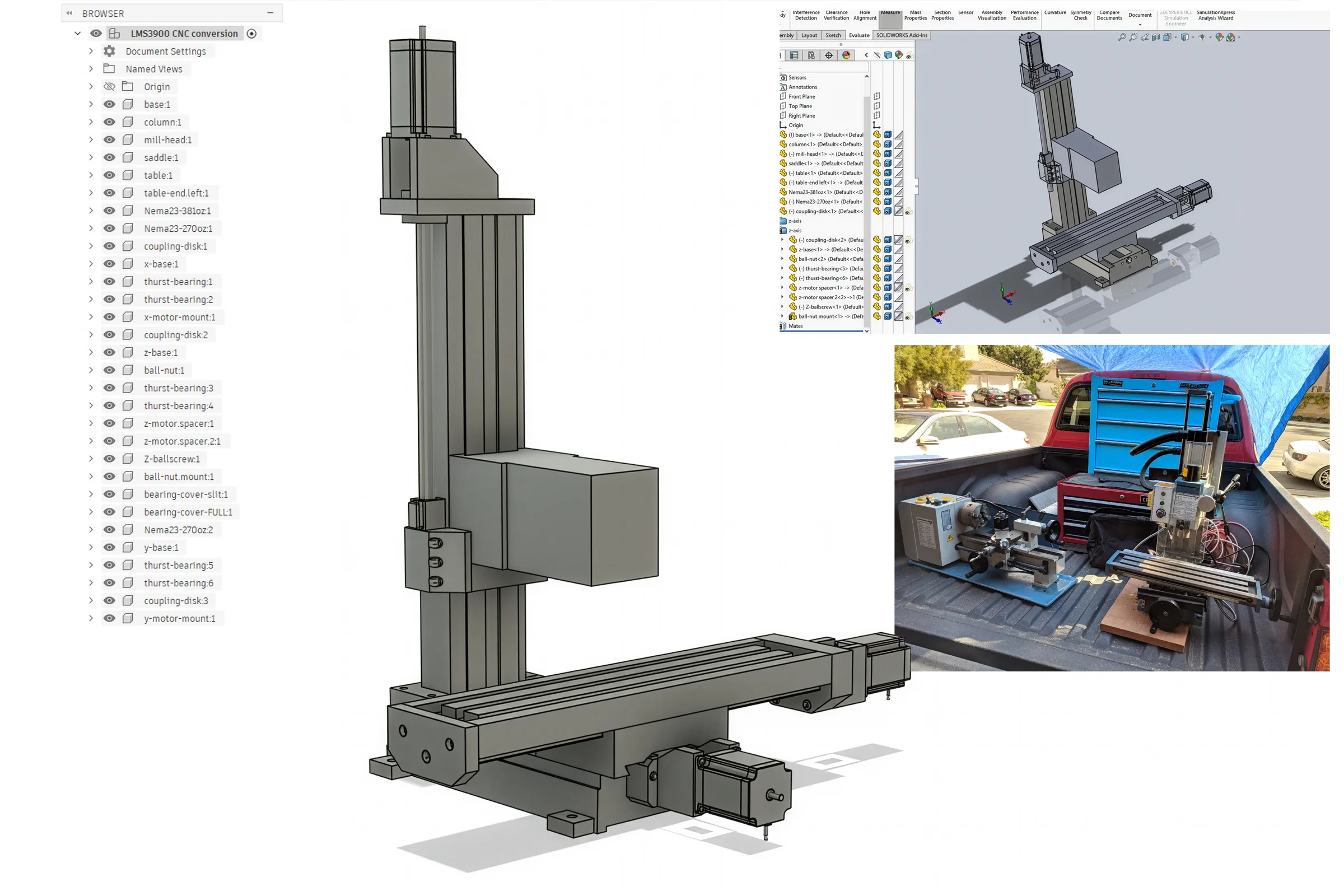
The Little Machine Shop X2 variant was a meaningfully better machine than the standard Chinese import. Beefier castings, tighter factory tolerances, acquired specifically as the CNC platform. By this point I had already modified two X2 mills extensively and understood exactly where the casting geometry allowed modification and where it didn't. That knowledge went directly into the SolidWorks design. The entire conversion: motor mounts, ballscrew end supports, scale mounts, coupling adapters, electronics enclosure brackets. All fully modeled before any material was touched.
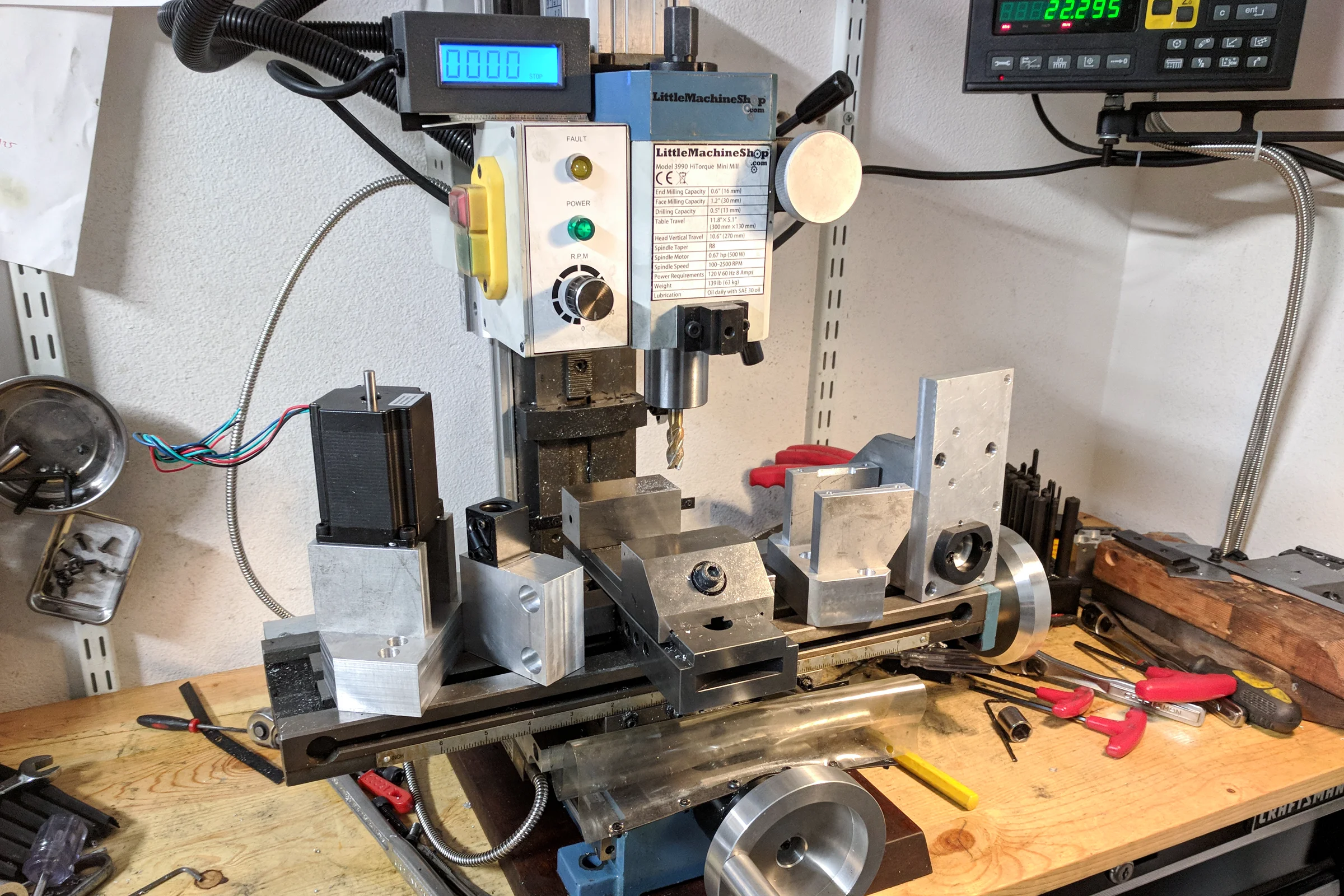
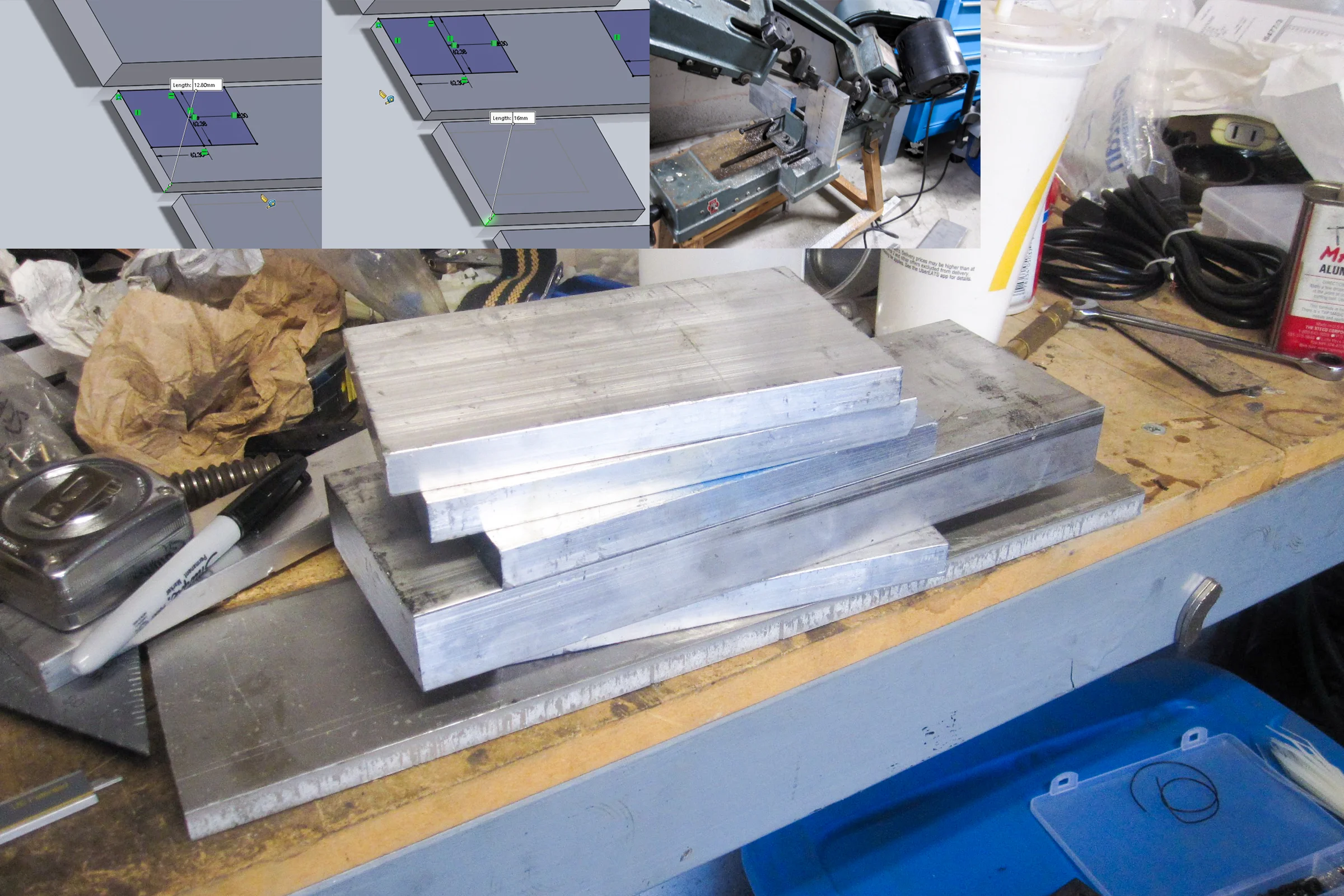
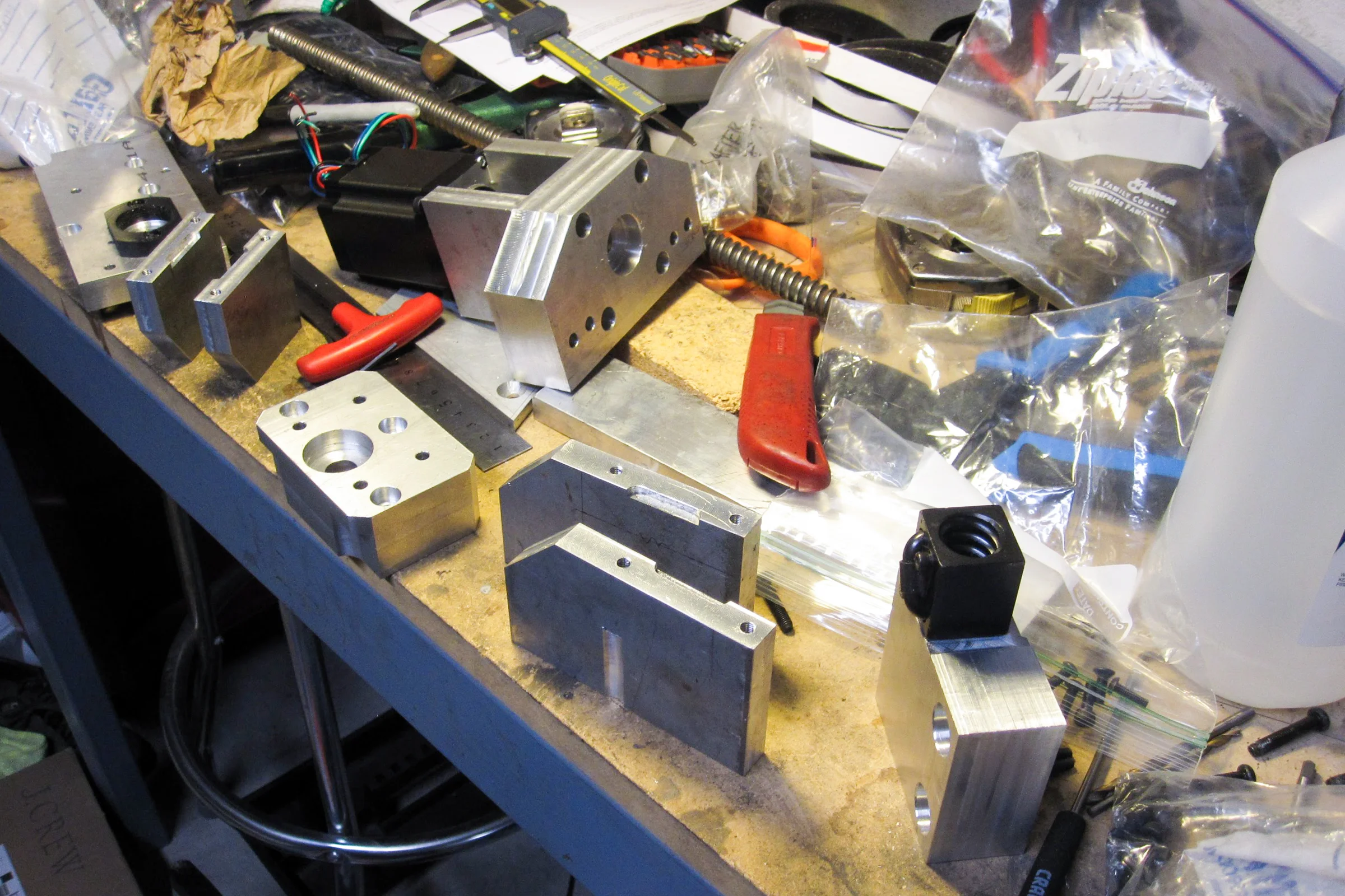
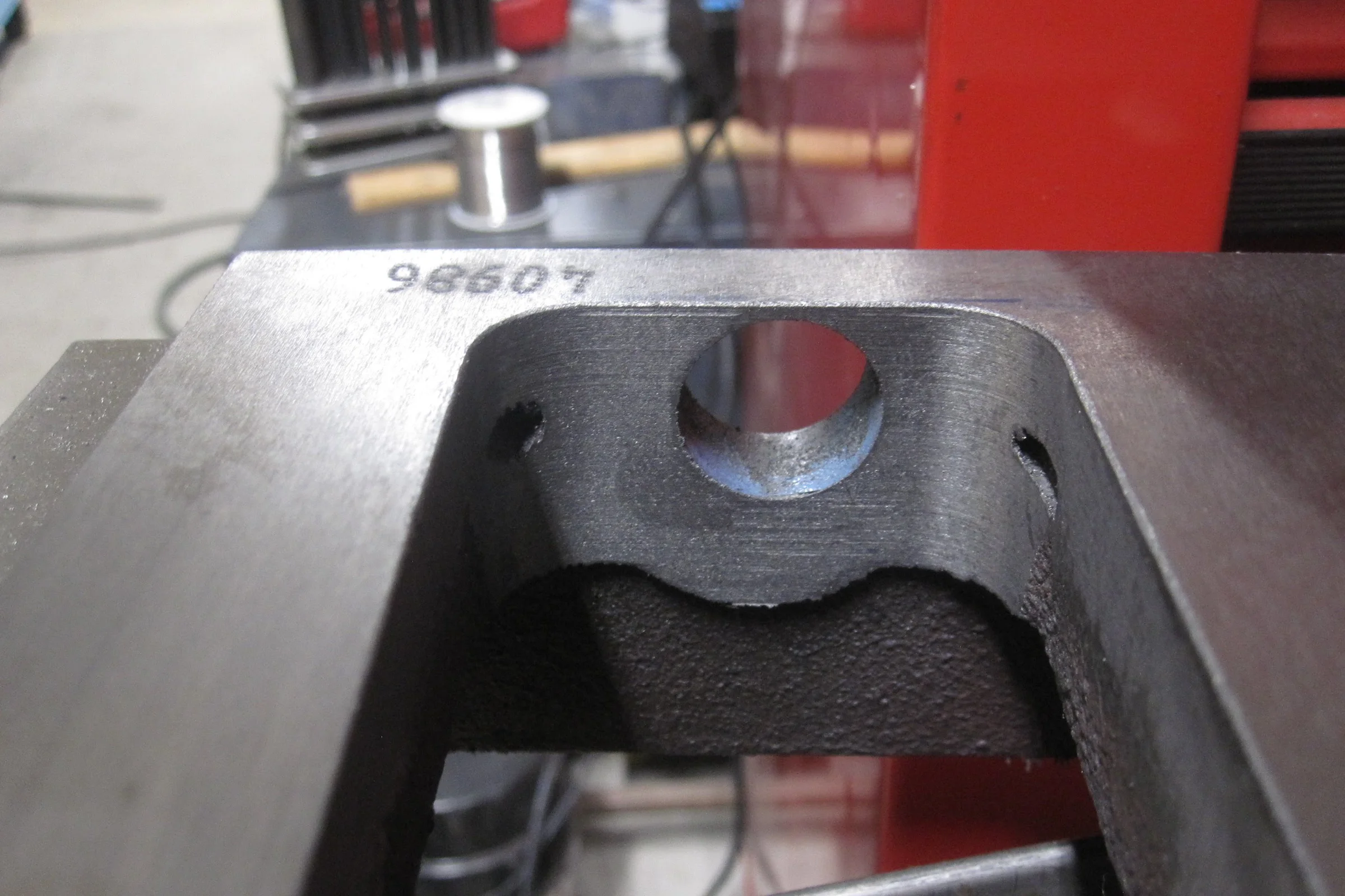
Because the ball screws were being repurposed from the super mill and I had already done similar casting modifications before, I knew exactly what aluminum parts needed to be machined and what cast iron clearance work the LMS mill would need. All the 6061 aluminum components were machined before the LMS mill was even torn down. Once the teardown happened, the cast iron clearance work was done on the now-bare machine, and everything was ready to assemble with the new components already waiting.
That sequencing was deliberate. Tearing down a machine and leaving it disassembled while waiting for parts to be machined is how projects stall for weeks. Having everything ready before the teardown meant the conversion moved in one continuous direction. Everything fit on first assembly.
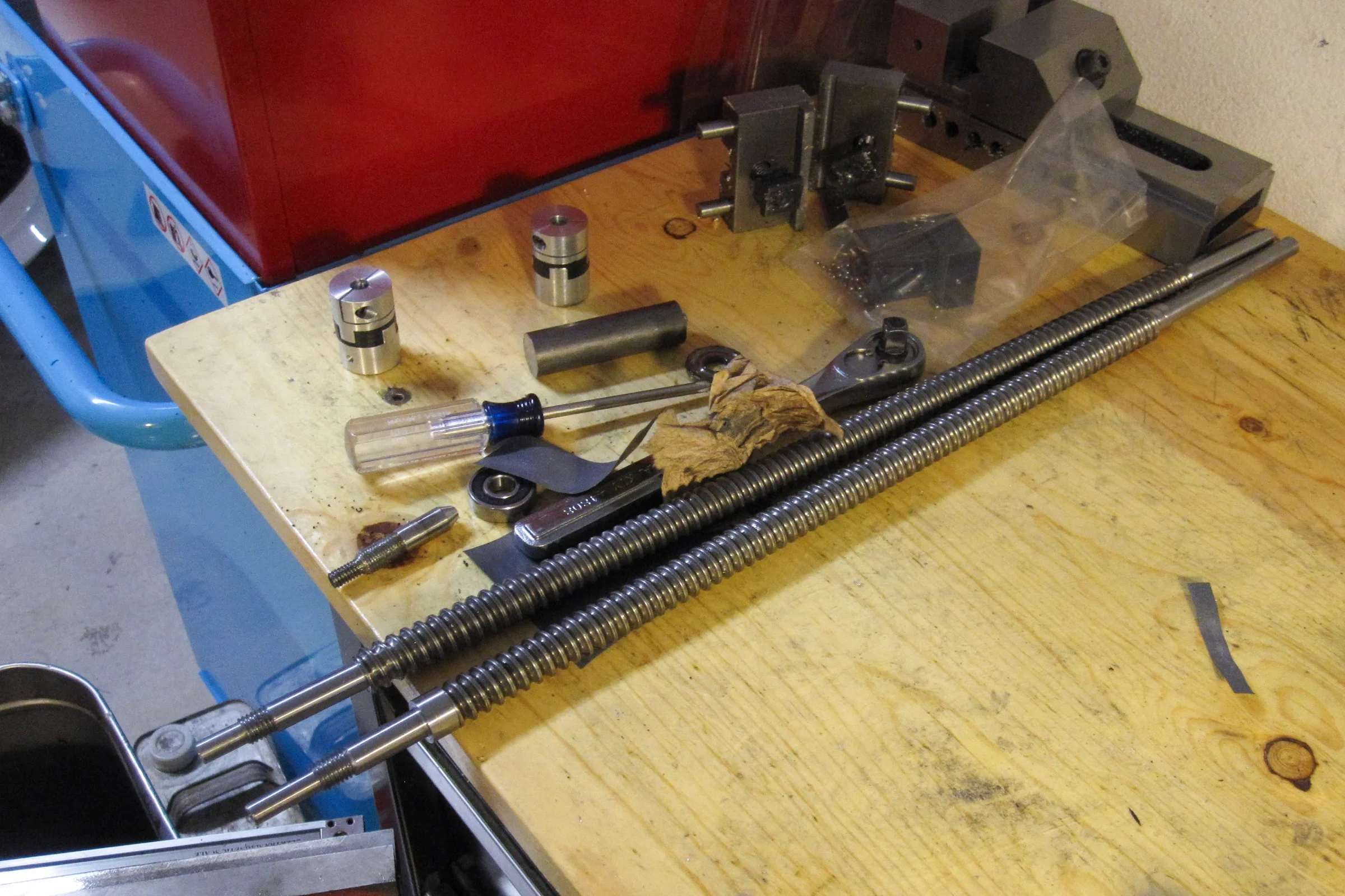
Compliance Couplings: Machined to Exact Spec
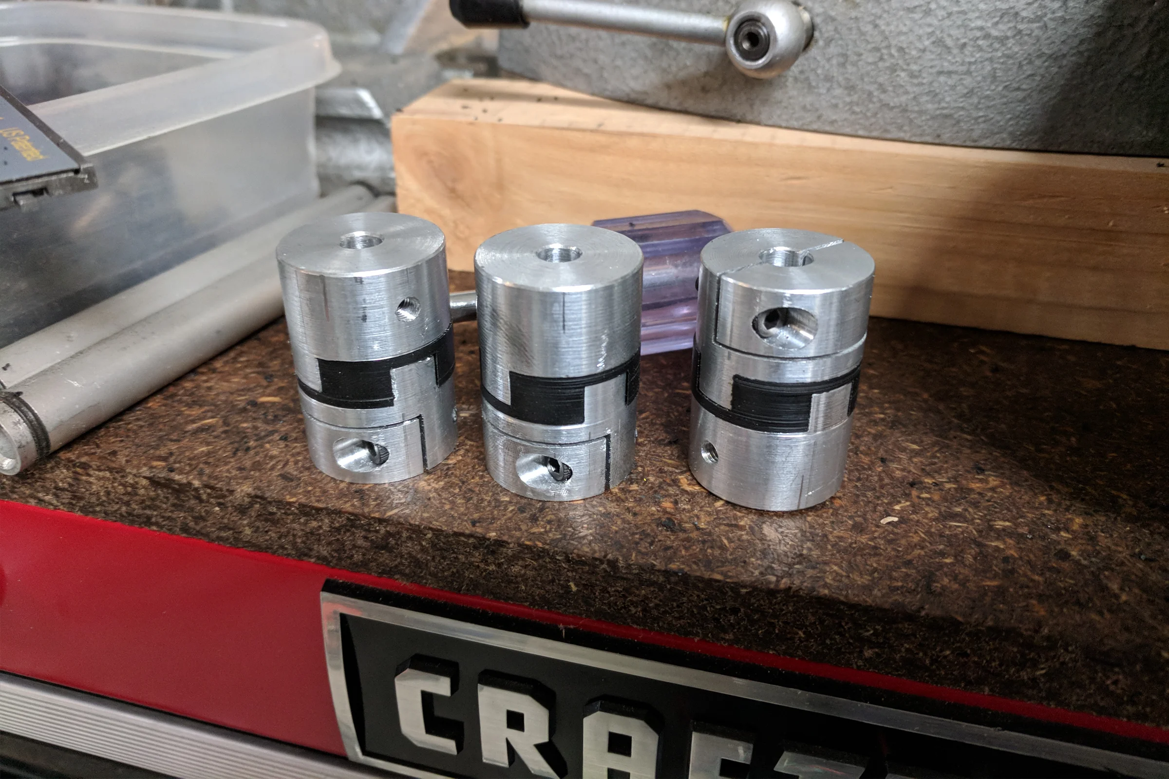
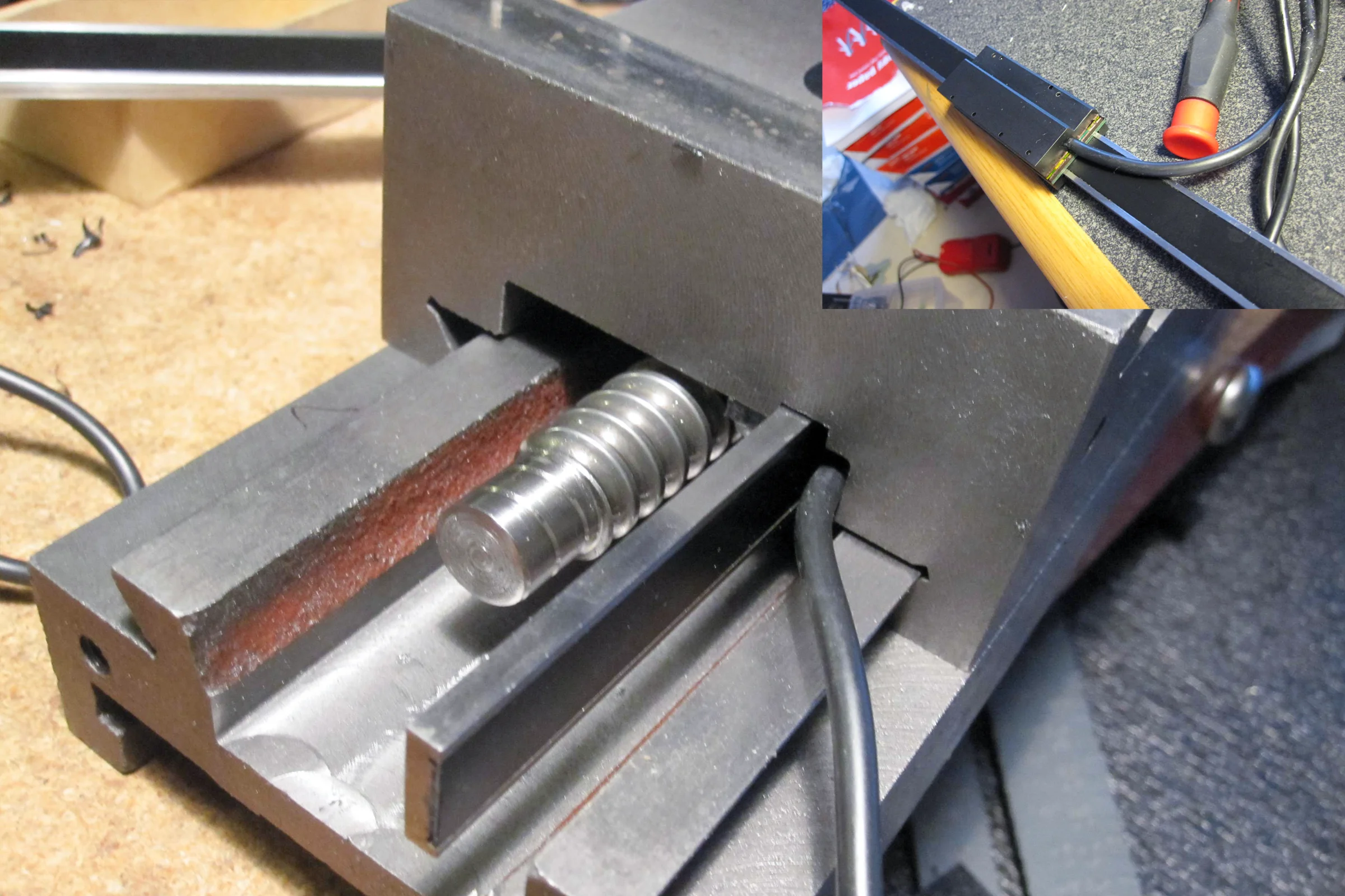
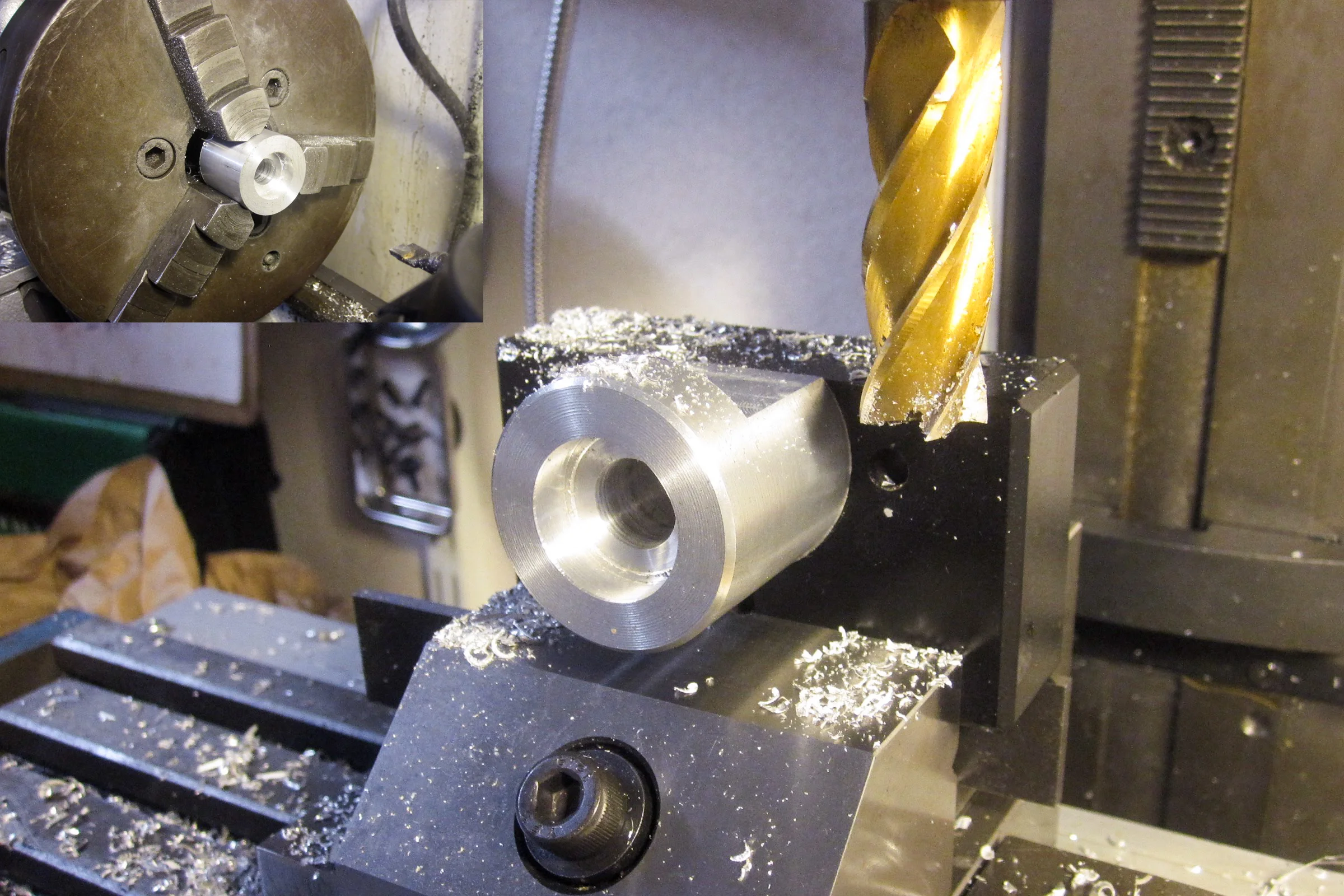
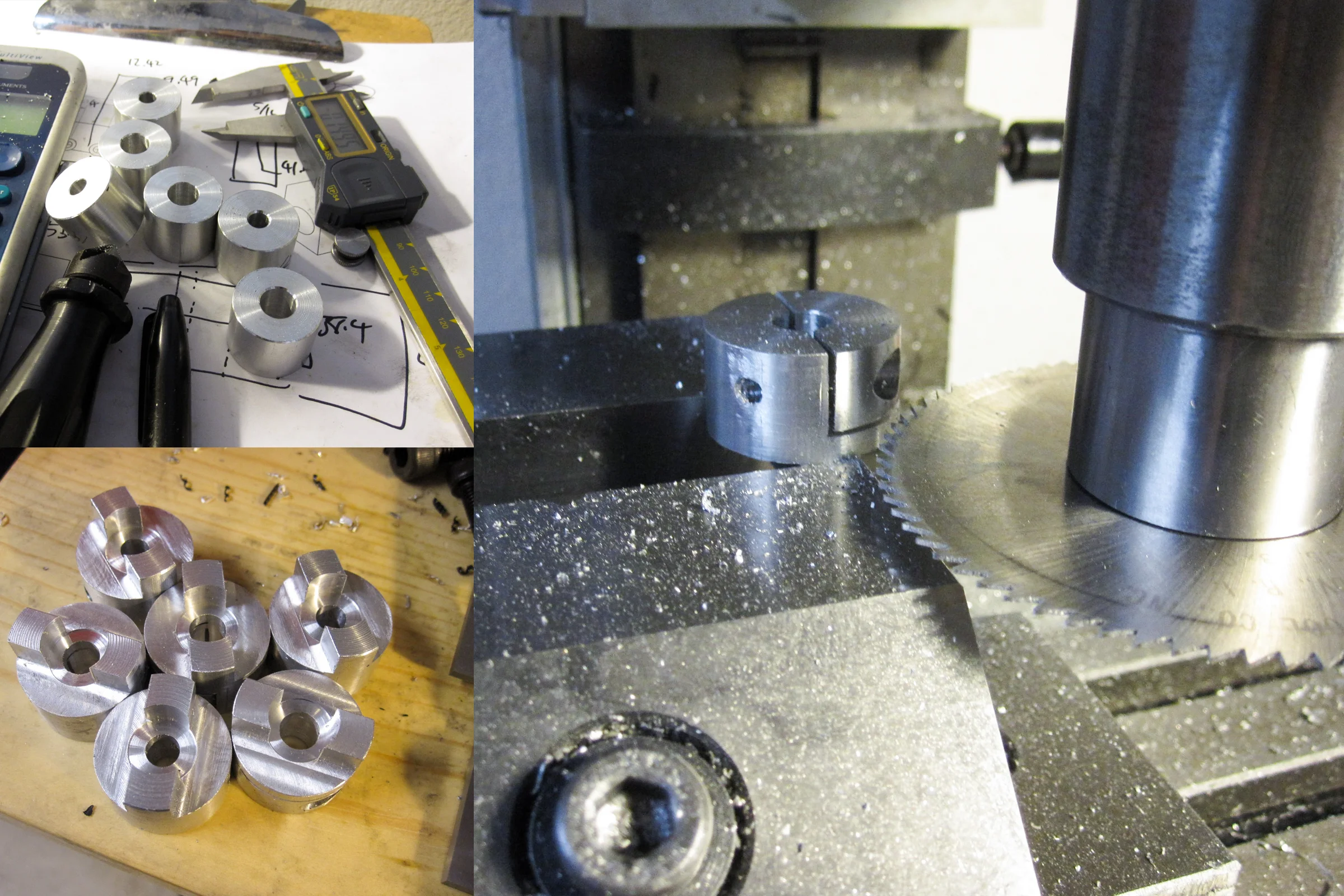
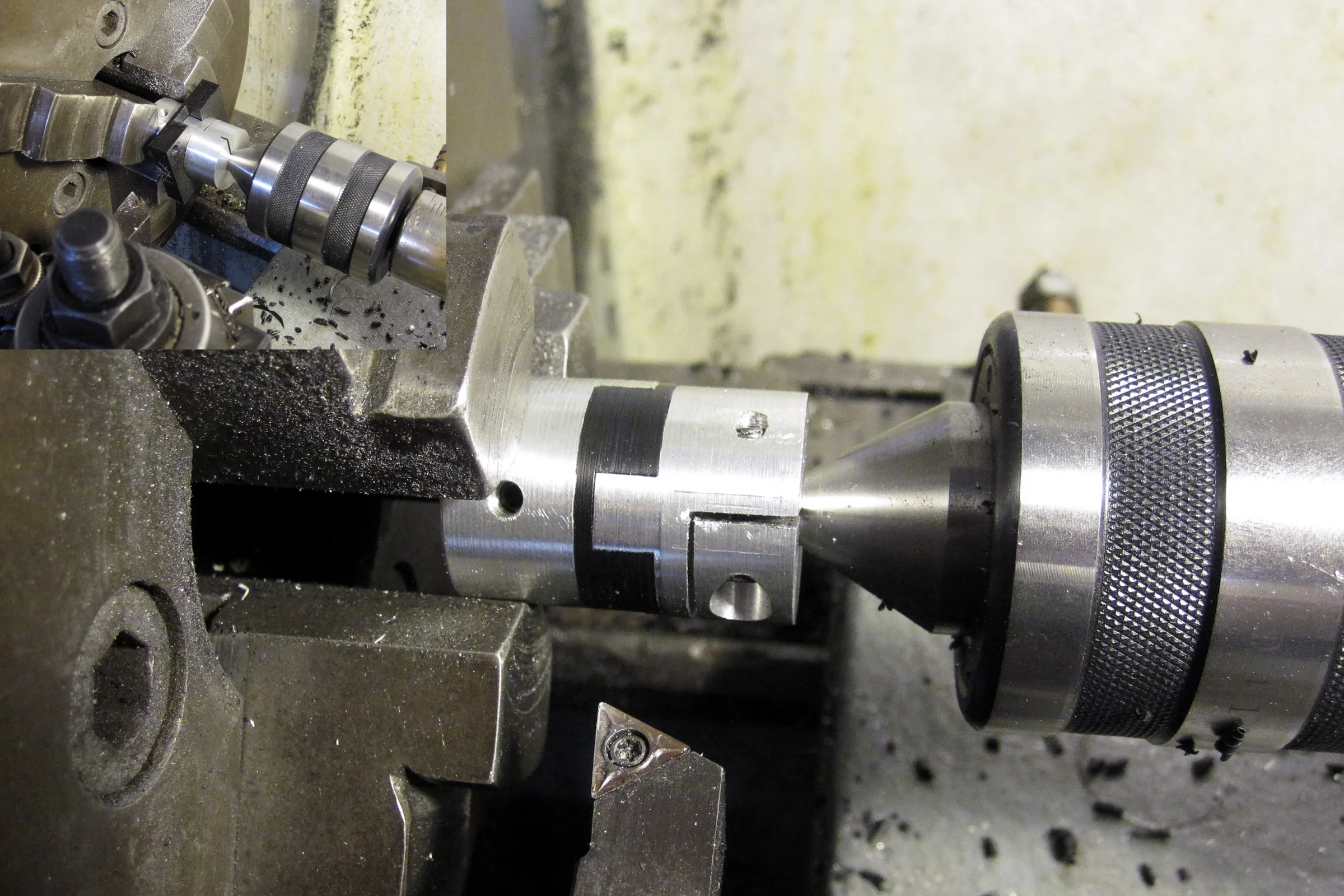
The ball screws repurposed from the super mill had already been turned to a non-standard spec for that application, so off-the-shelf couplings wouldn't fit anyway. Machining them from scratch was the practical solution. The design was an Oldham coupling: aluminum flanges on both shaft ends, Delrin center sliding disk in between.
Delrin was chosen for its low coefficient of friction for smooth lateral compensation, good dimensional stability, and clean machinability with standard HSS endmills. It was also already on hand. Critically, it acts as a designed sacrificial failure point. On a crash, the Delrin disk fails before the ballscrew or motor does.
The interference fit between the disk and flanges determines backlash. I referenced Machinery's Handbook and targeted approximately 0.04mm interference: tight enough for zero backlash under cutting loads, light enough to press in by hand. Delrin channels machined slightly undersized, aluminum teeth slightly oversized. Getting that fit dialed in took a few iterations on the super mill, which was the whole point of making these from scratch.
Electronics: Specced and Integrated from Scratch
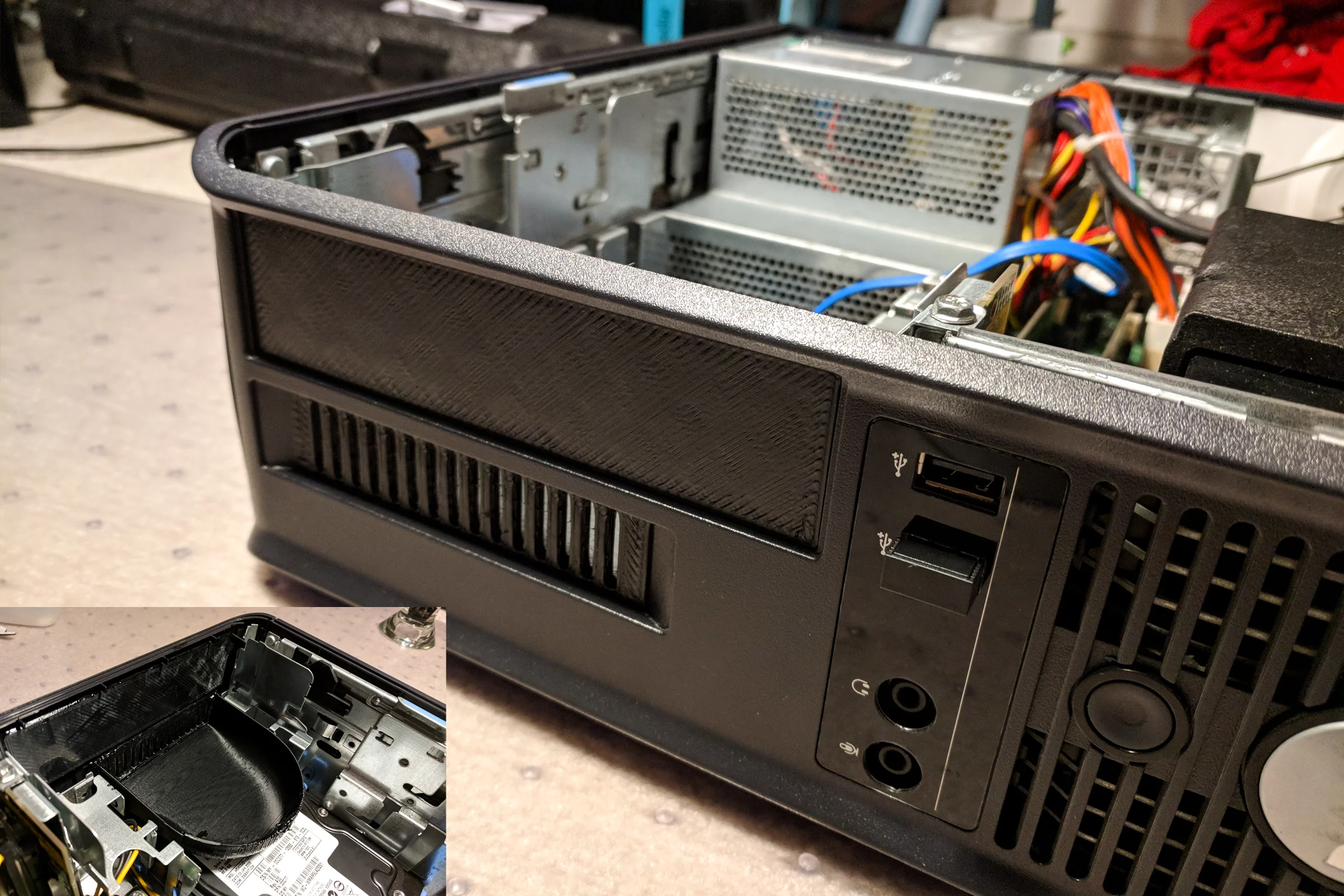
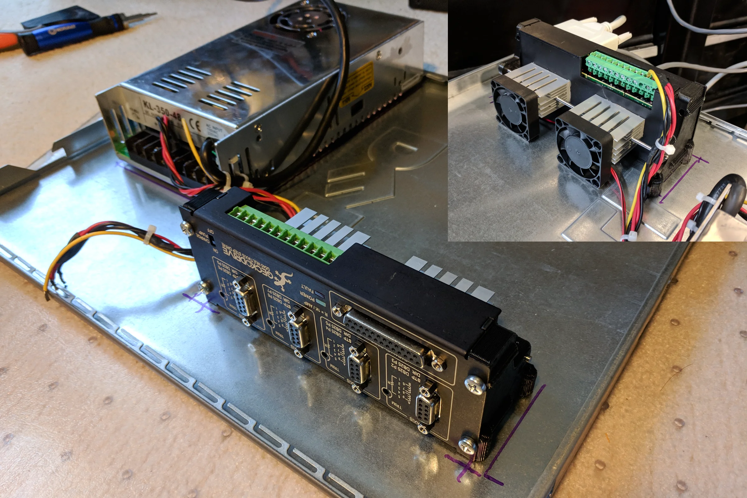
Years of building, modifying, and hacking 3D printers meant stepper motors, drivers, and motion control were already familiar territory before this project started. That background made it possible to select and spec every component independently rather than buying a packaged kit. Geckodrive G540 chosen for proven reliability, good cost-to-performance ratio, and straightforward configurability. An older small form factor computer sourced specifically for its parallel port, required for the G540 and no longer standard on newer hardware, and because older Windows with minimal background processes runs Mach3 more reliably than a modern machine would.
After removing the unnecessary hardware from the computer case, the CD-ROM drive and unused expansion cards, there was more than enough room inside. Designed and 3D-printed custom mounting brackets and mounted the Geckodrive directly inside the computer case. Repurposed old CPU heatsinks and fans to build a custom cooler for the drive. A dedicated 48V power supply for the motor drivers was also integrated inside the case alongside the computer hardware. The entire CNC control system, computer, Geckodrive, and 48V motor supply, lives inside one slim computer case.
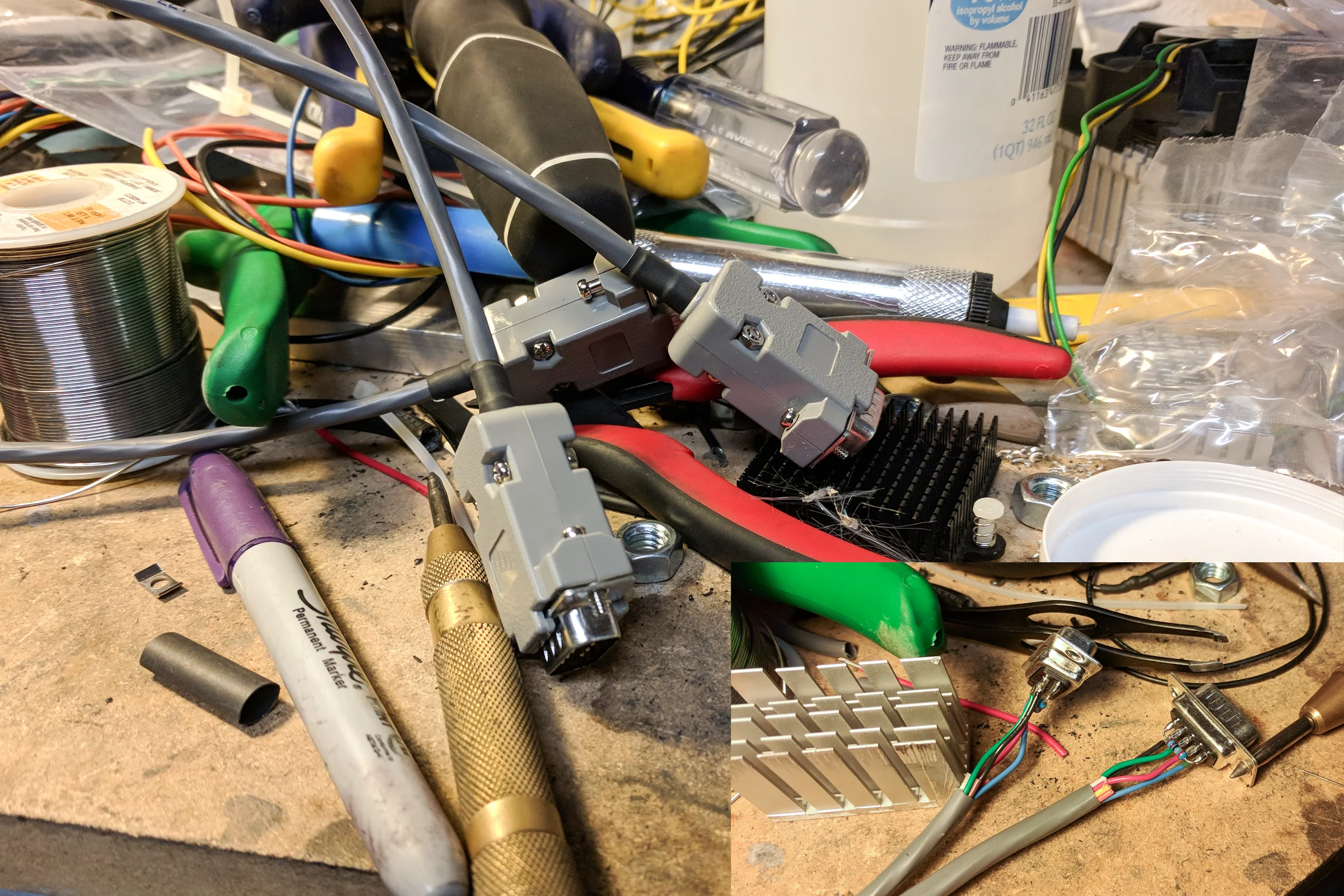
All motor wiring done by hand. Configured soft limits in Mach3, ran test programs, and after a small amount of troubleshooting the machine was up and cutting.