S2000
Fabrication
Program
Not a car build. A multi-year fabrication program with a single operating principle: if the problem is hard enough and the constraints are tight enough, the solution reveals itself through the physics. The car was never the point. It was the problem generator.
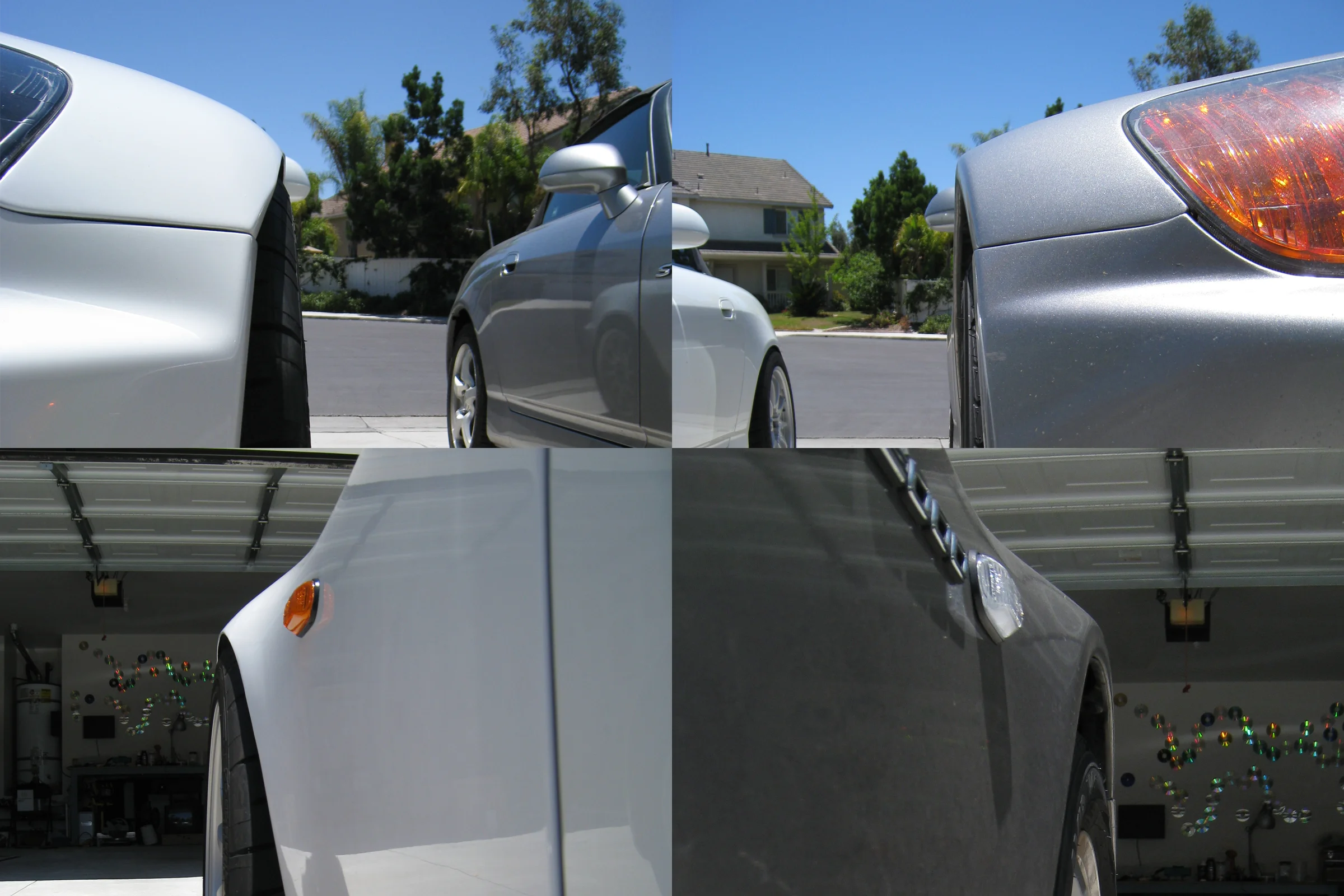
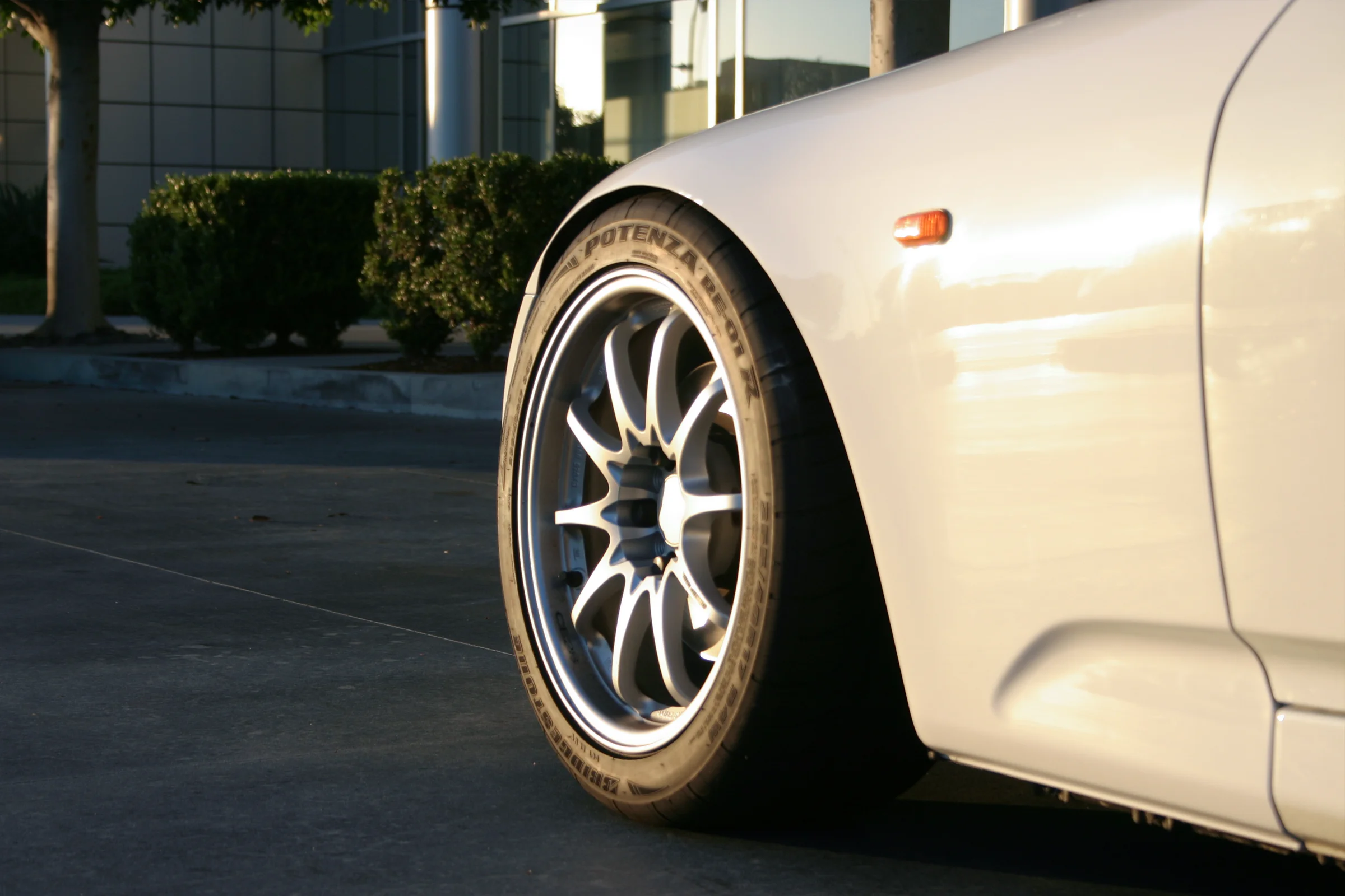
Fender Flaring, First Time Metal Shaping
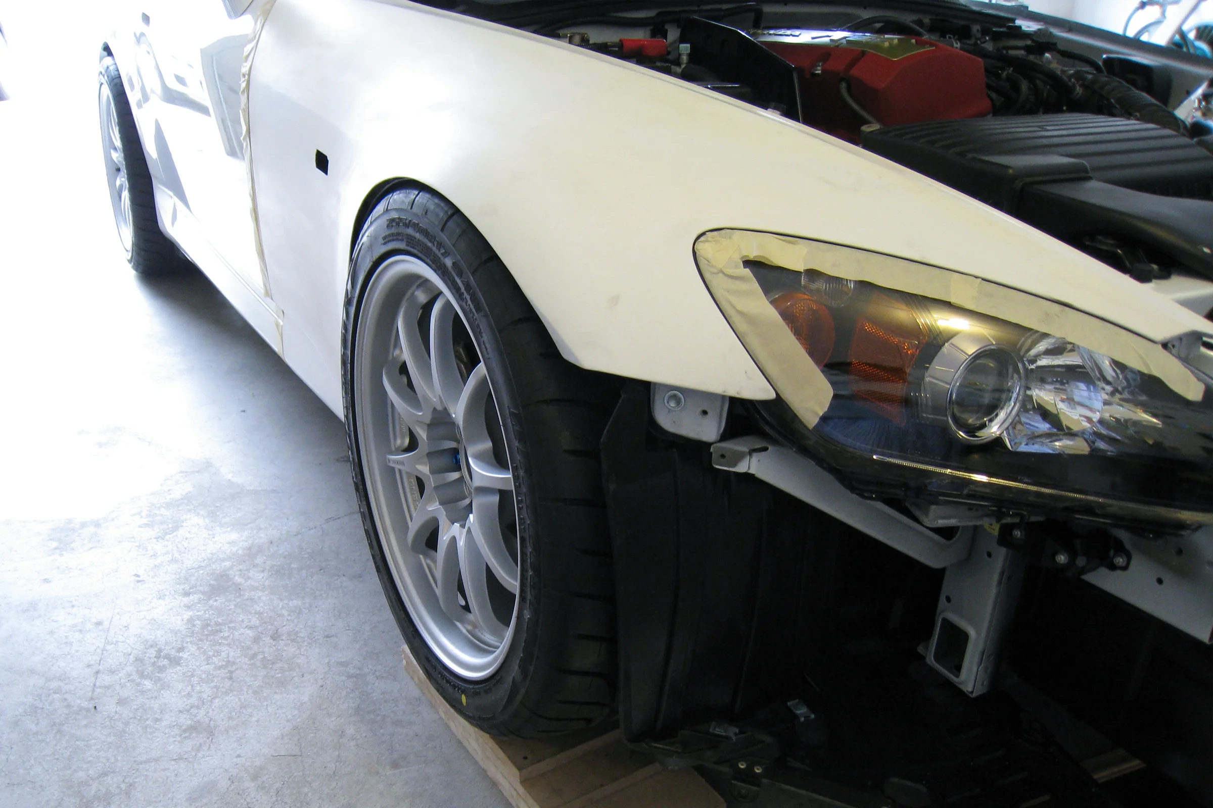
The AP1 S2000 was known for snap oversteer. Honda revised the AP2 with updated suspension geometry and larger rear tires to dial in more understeer. The separate pursuit, common in the track scene, was fitting wider tires on lower-offset wheels front and rear to maximize grip and push the stance out. Getting a wider front tire under the factory fender on a low-offset wheel required reshaping the arch entirely: not rolling it, reshaping it. The vertical lip had to be hammered flat and transitioned smoothly back into the bumper line. Tuner shops charged around $2,000 total for both sides at the time, not including paint. Aftermarket fiberglass fenders existed but the fitment was poor enough that body shop correction costs erased any savings, and the fiberglass arch still had a vertical lip that would crack on tire contact rather than bend like factory steel.
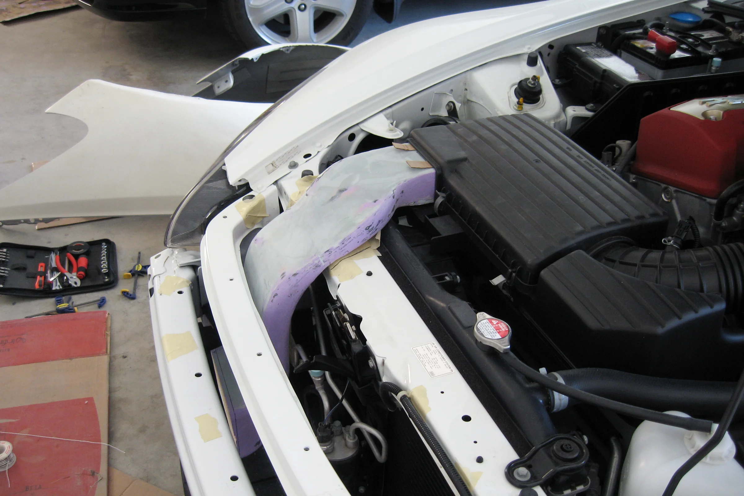
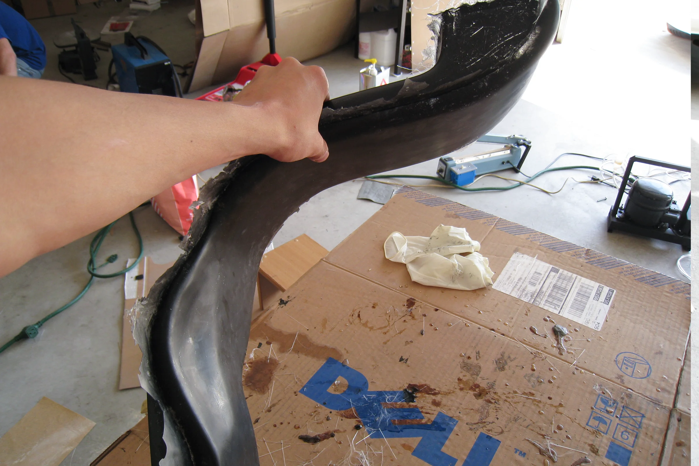
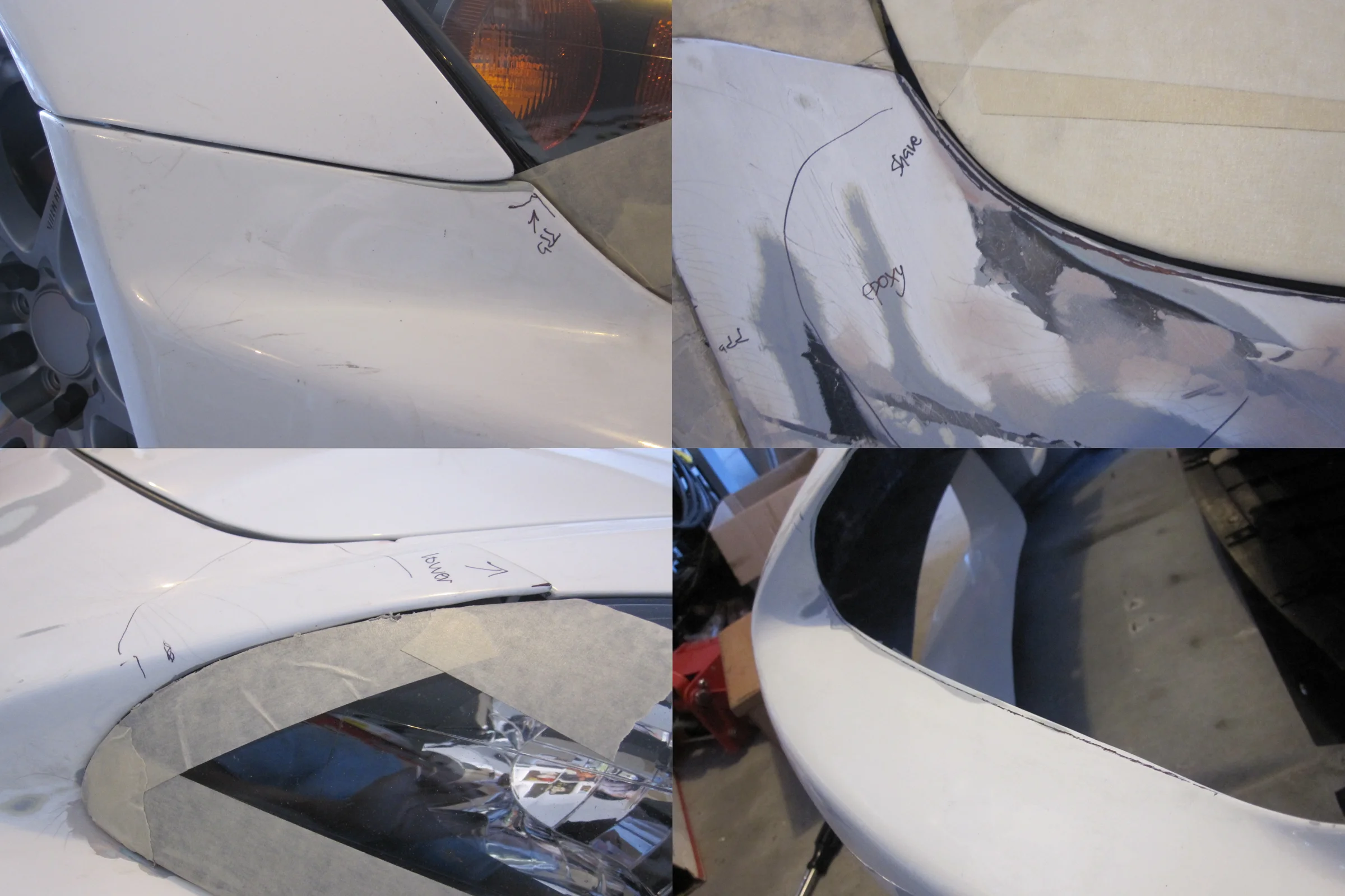
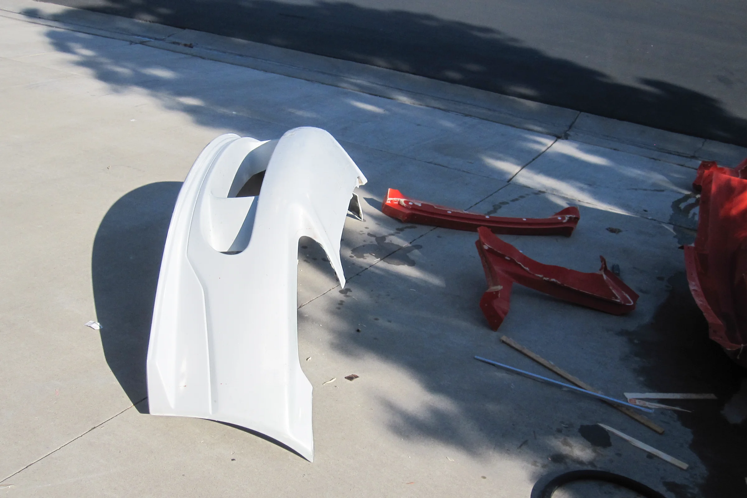
Having watched enough fabrication television to understand the basic physics of metal shaping, the decision was to buy a hammer and dolly set and teach myself on a spare set of damaged factory fenders sourced from Craigslist. The previous owner had lowered his car without flaring, and the tires had caught the fender arch and bent it, exactly where the work needed to happen. The damage was the starting point, not a problem.
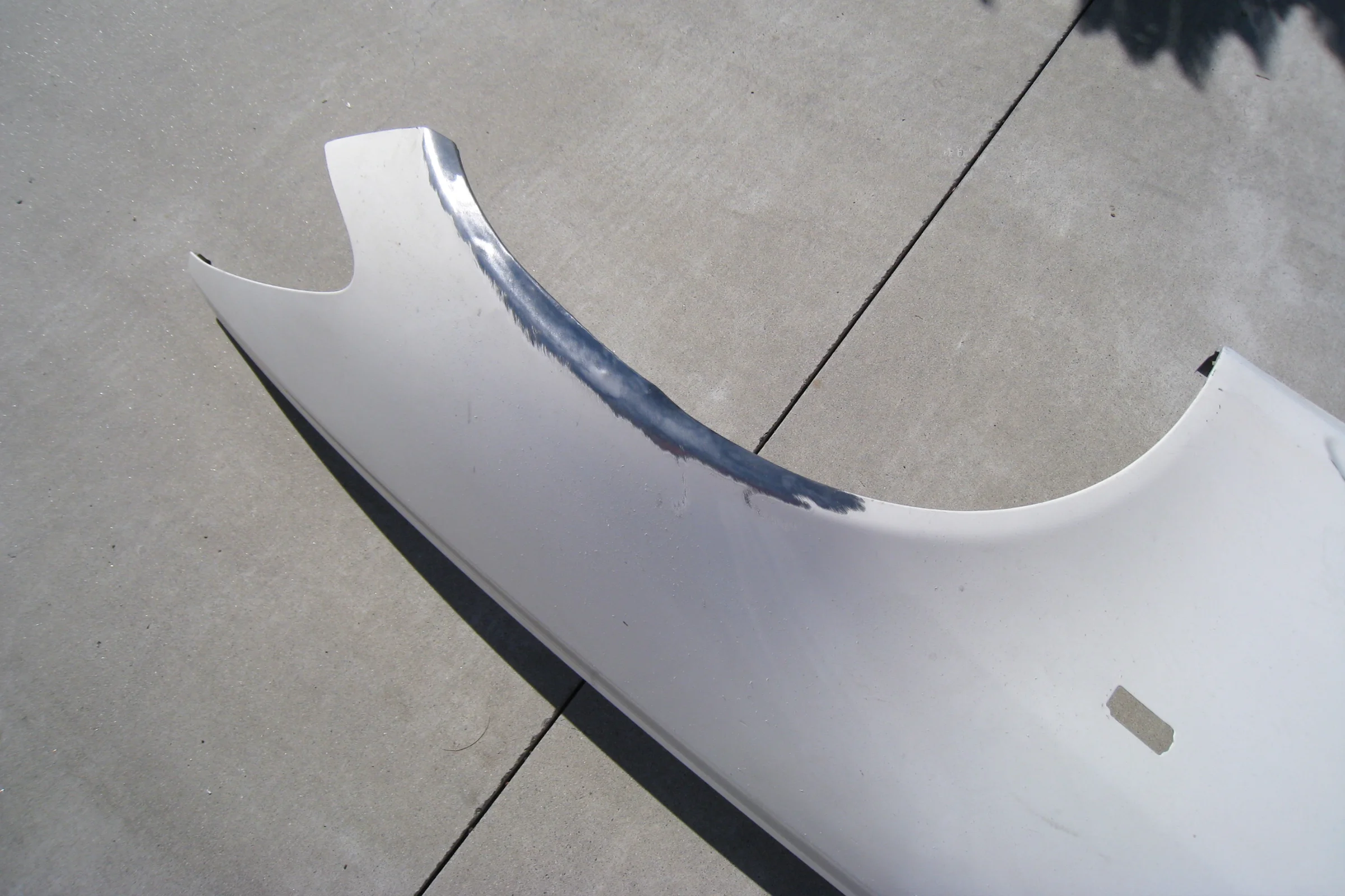
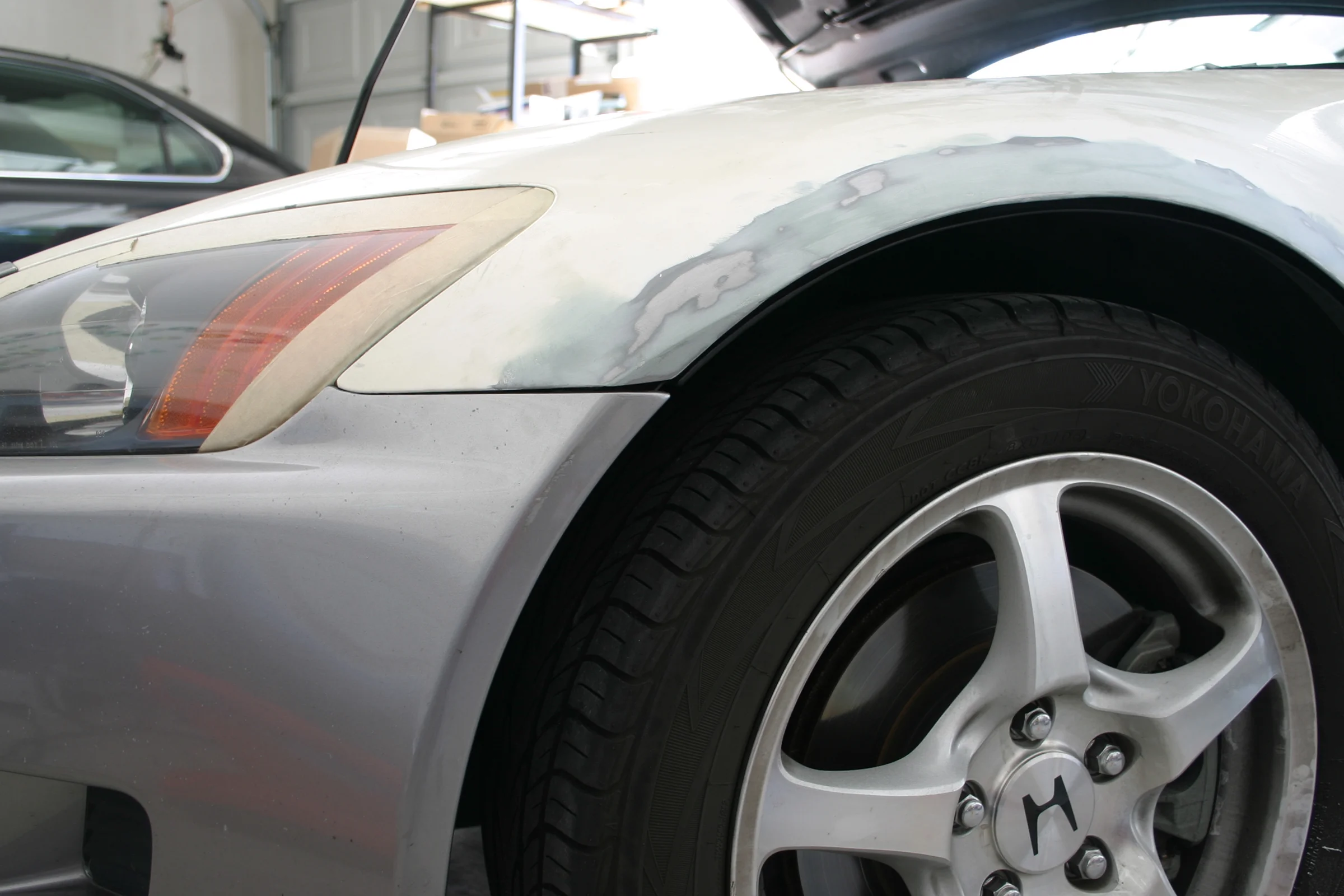
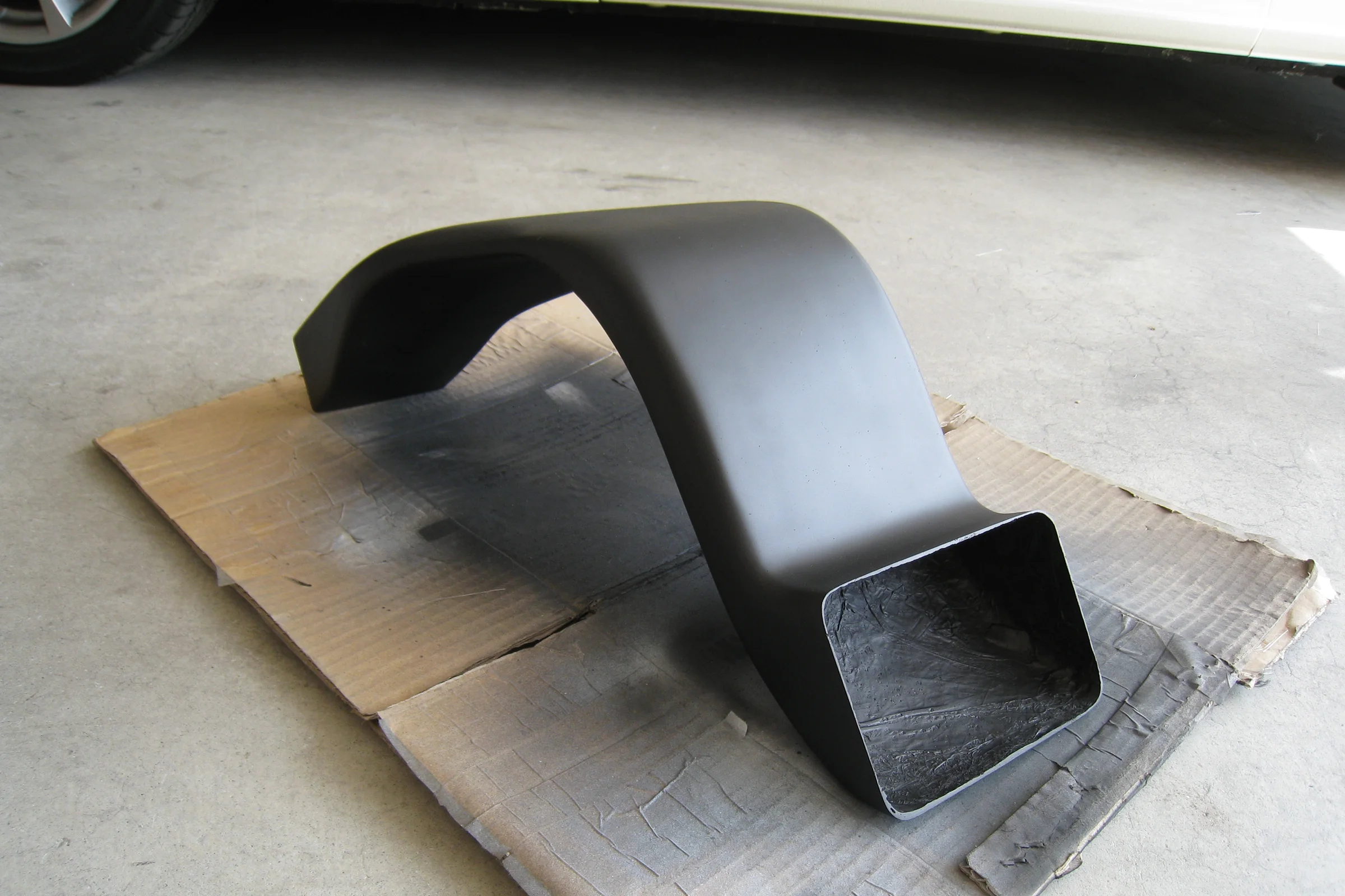
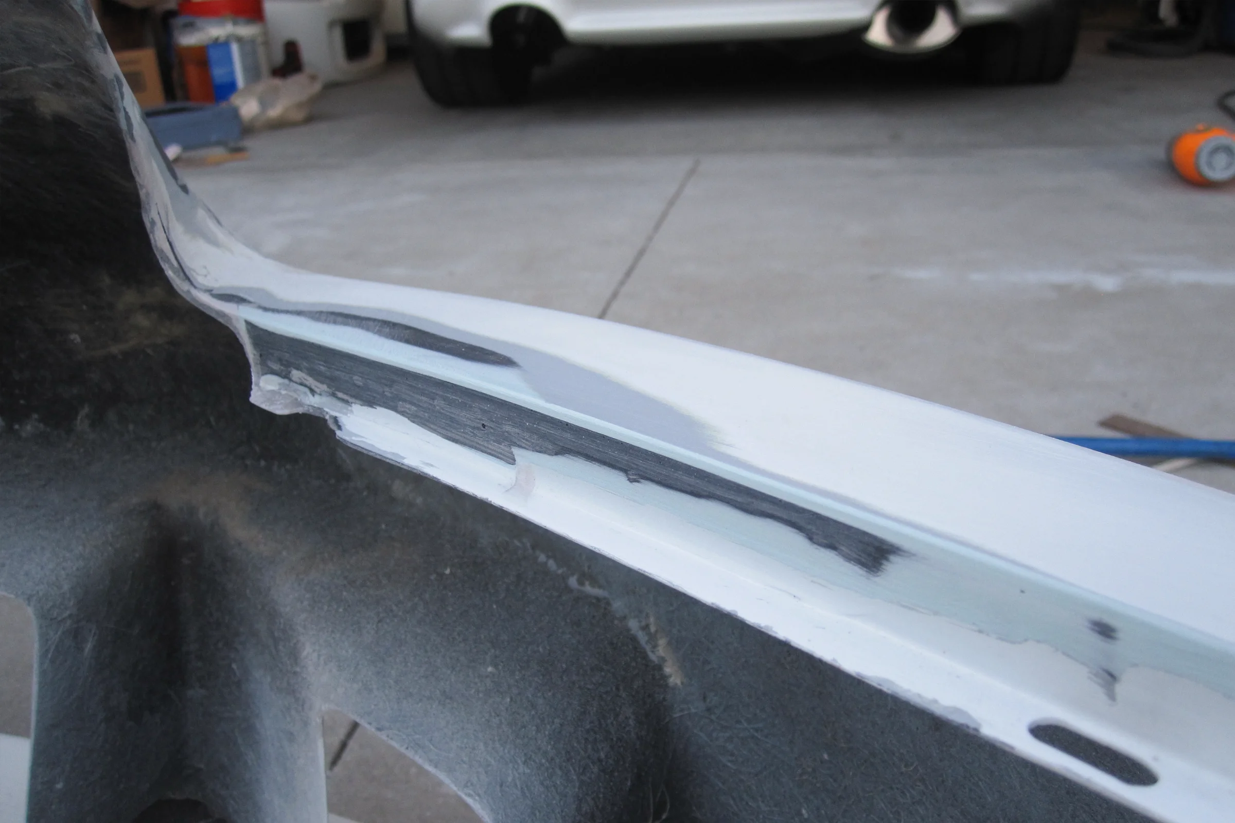
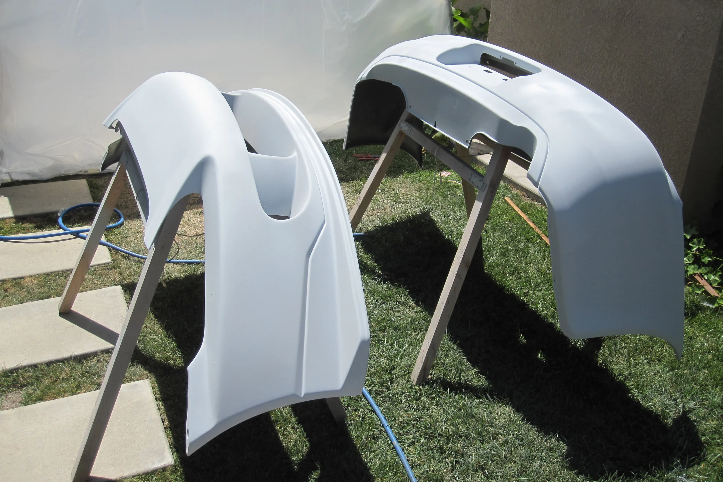
Process: wire wheel the rusted area clean, flatten the existing damage first, cut the fender liner tabs that would interfere with the new arch shape, then use heat to gradually stretch the vertical lip outward and shape it into the natural curve of the wheel arch with a curved dolly. Where the flared arch met the front bumper, a stress-relief cut allowed the corner to pull cleanly, followed by a small transition triangle folded inward to blend the new flare angle back to the original bumper line. Tack-welded the cut closed afterward and ground smooth. First time ever doing metal shaping. The process came out clean.

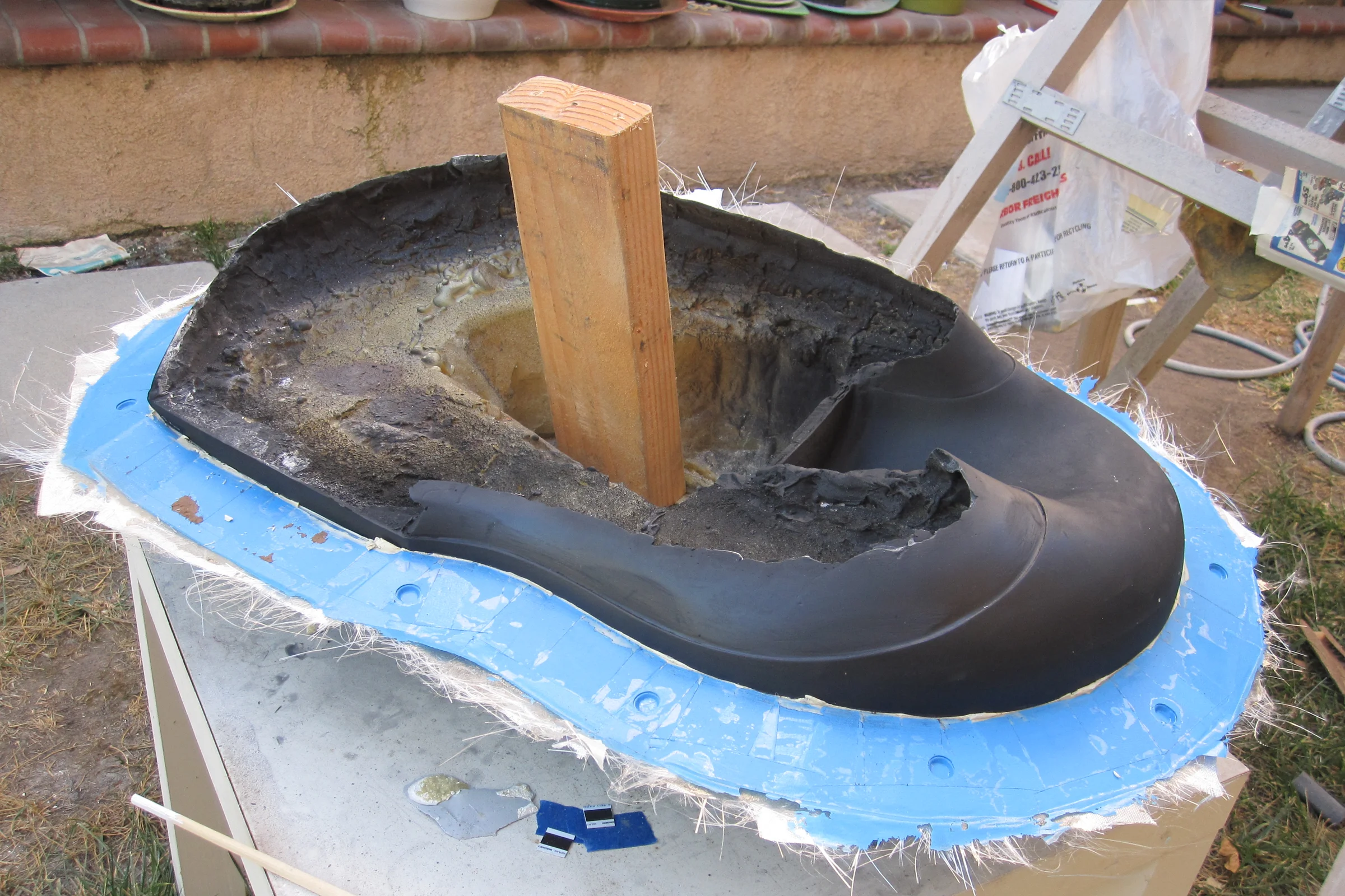
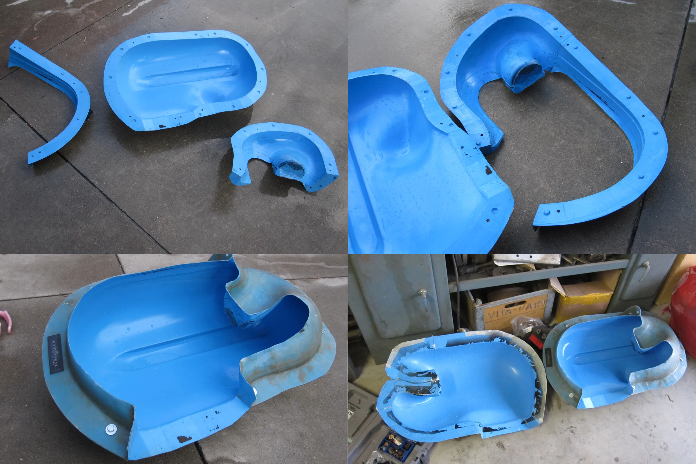
After the fenders were finished and fitted, a five-part fiberglass mold was pulled from them, the geometry had enough compound curves and draft complexity that a simpler approach wouldn't have released cleanly. Time and cost meant the mold was never used to replicate the fenders in composite, but building it taught lessons in large-panel parting line strategy that carried directly into every mold project that followed.
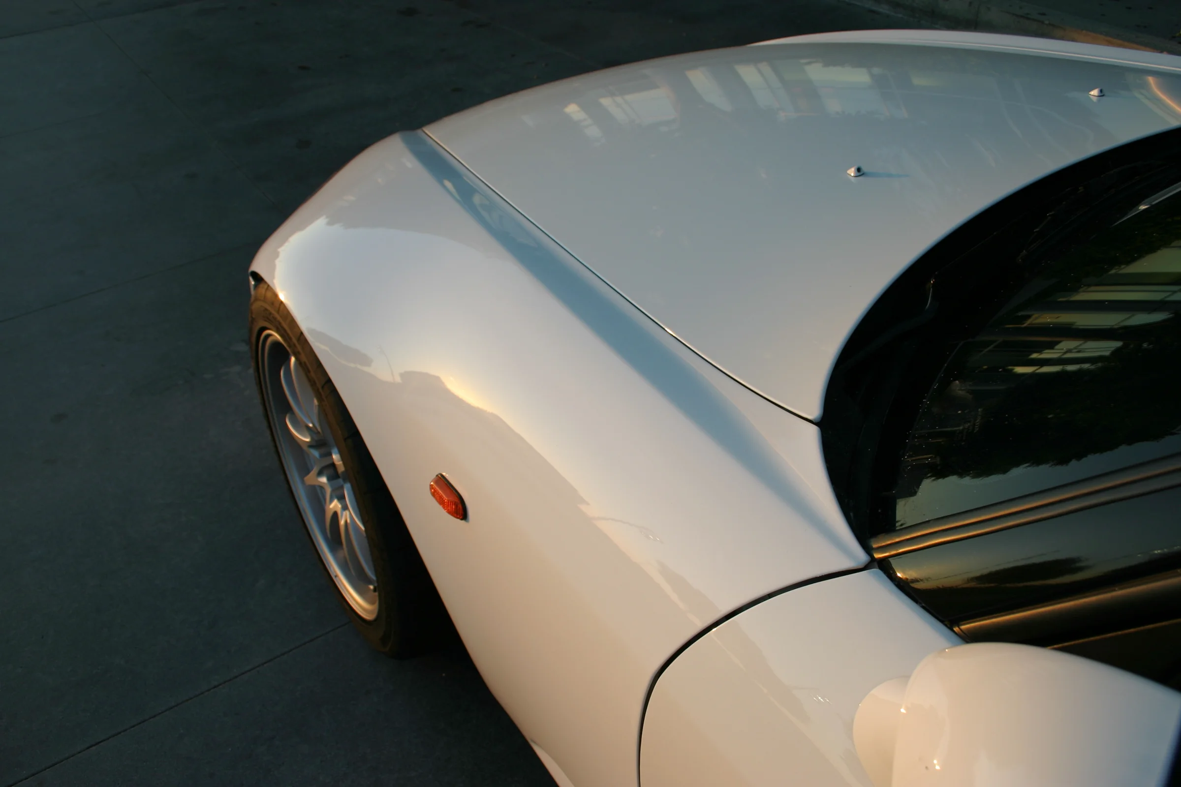
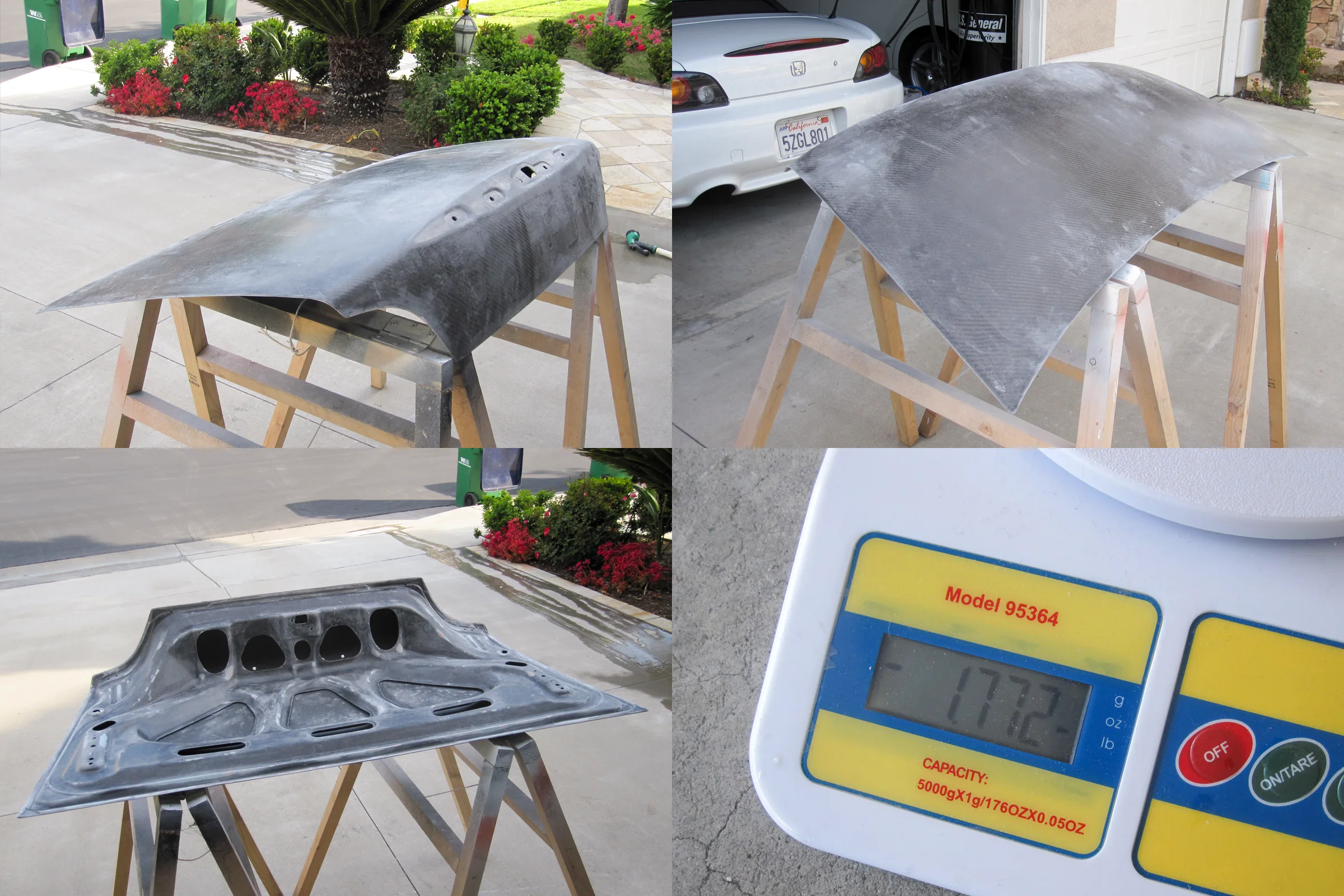
Carbon Fiber Trunk, Full Carbon, 1.77 lb
Carbon fiber replacement trunks for the S2000 were available from Japan at $2,000 to $4,000. Before deciding to build one, the first step was inspecting the ones already in the community. At car meets, owners were asked to open their trunks so the layup could be examined at the cut edges and mounting holes. What became apparent quickly: most trunks sold as carbon fiber were not. The outer skin was carbon. The structural layers underneath were fiberglass, often chopped strand mat, the heaviest and cheapest option. The finished weights confirmed it. Real carbon fiber parts are only lightweight if you push the material to its actual limits. These weren't. They were fiberglass parts with carbon on the face.
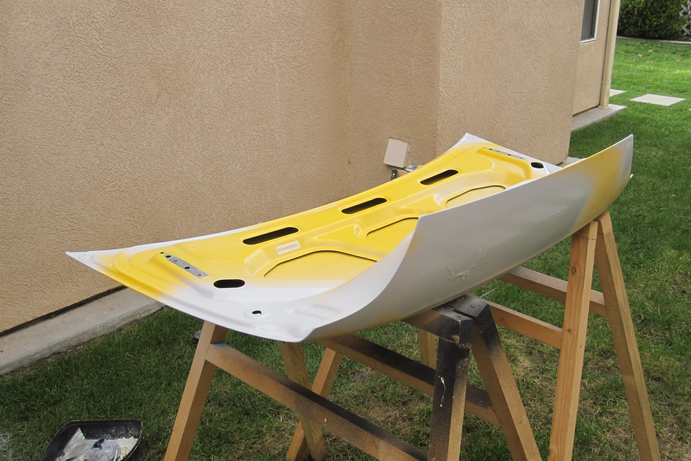
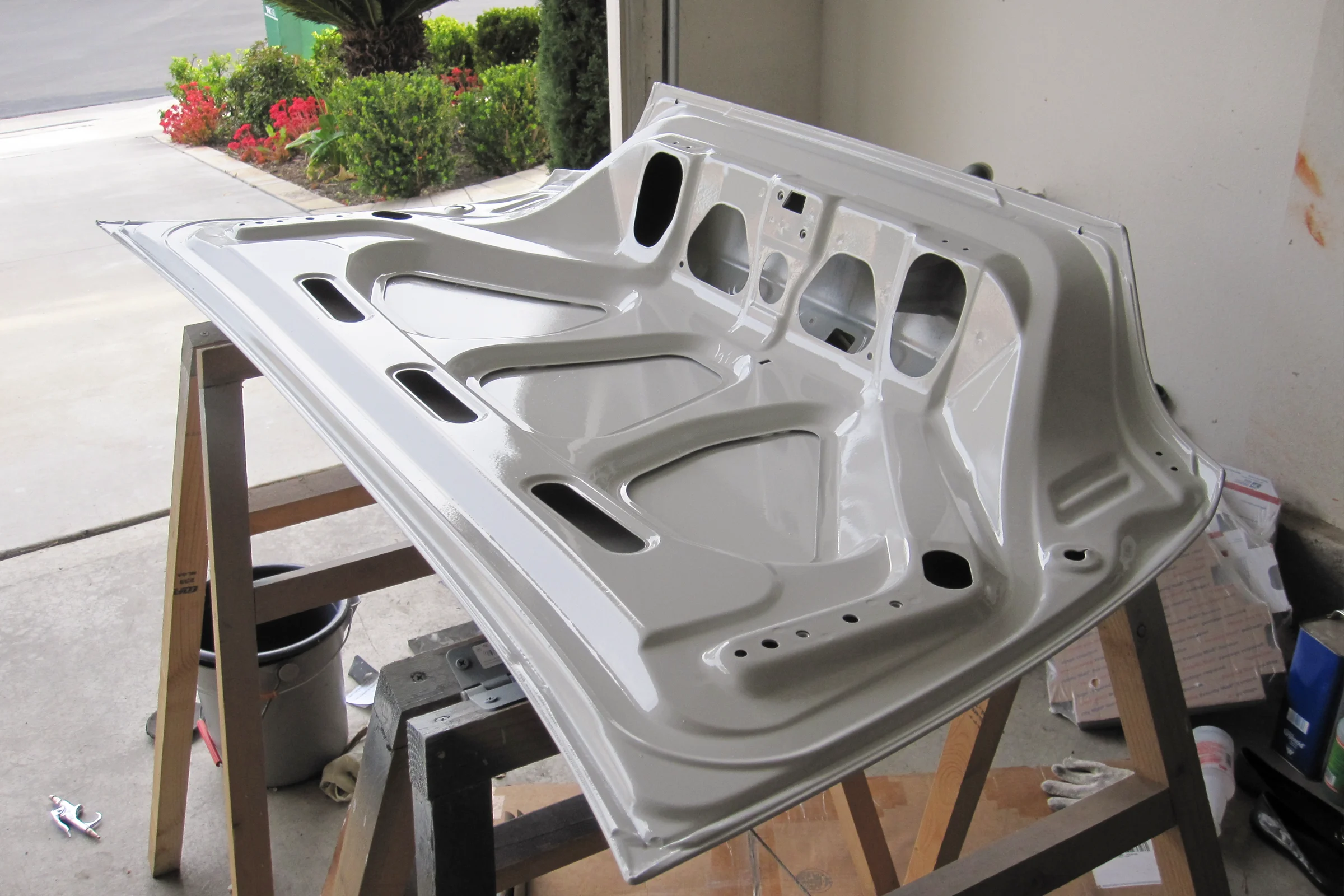
The goal was to build a trunk that was actually carbon throughout. A donor trunk was sourced, and the only modification before molding was shaving the keyhole and Honda emblem mounting holes. S2000 owners rarely use the keyhole, and debadging the car for a cleaner look leaves two open holes where the emblem mounts. Neither had a place on a trunk built to be the lightest possible version of itself. The keyhole shape was traced onto sheet metal, a filler disc cut and welded in, the emblem holes tack-welded shut and ground smooth. The plug surface had to be exactly what the final part would be before the mold came off it. The prepared surface was sprayed in epoxy primer for molding.
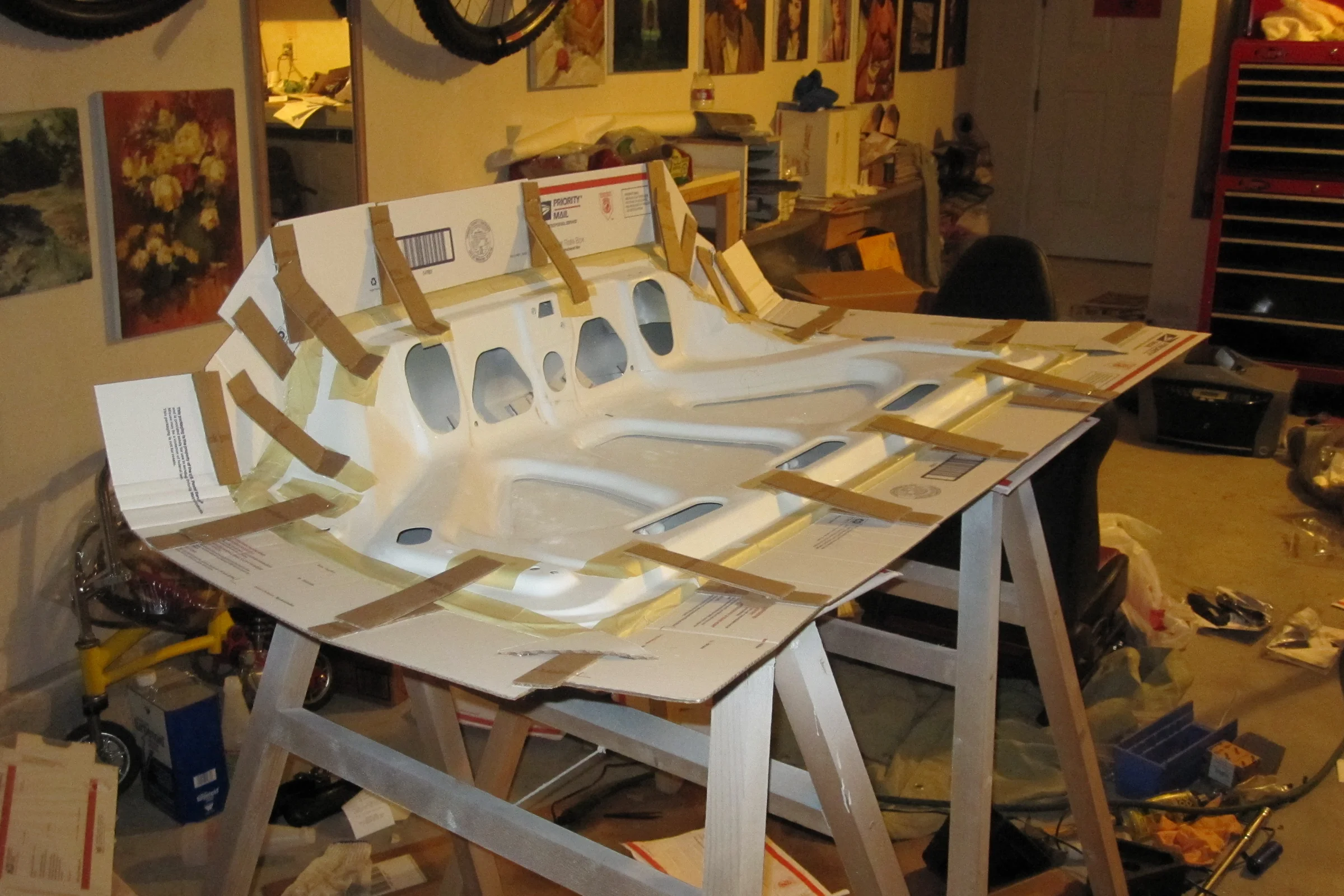
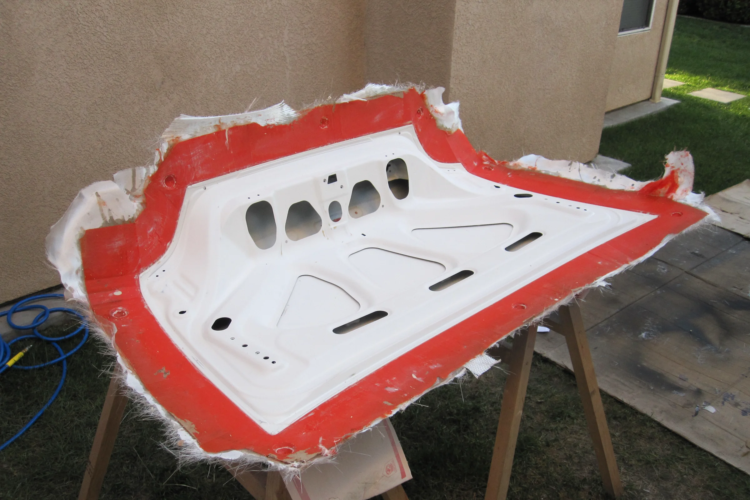
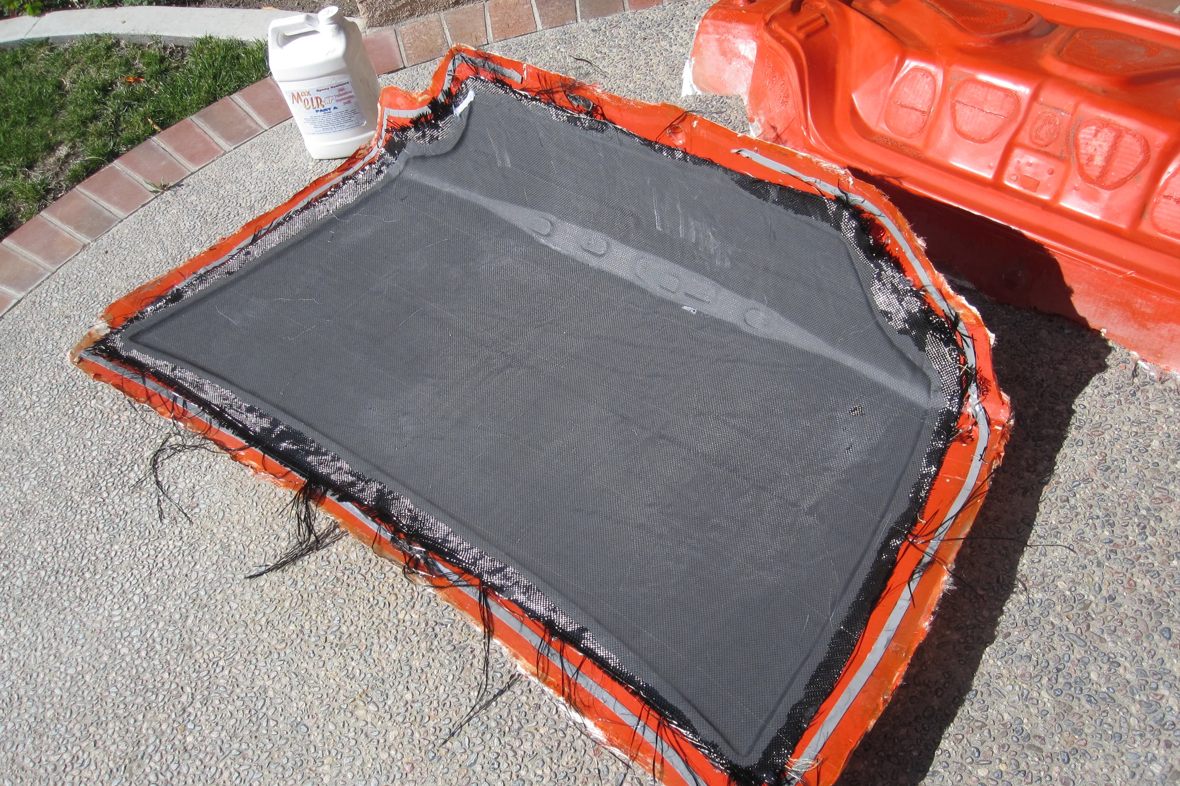
Two separate molds: one for the outer skin, one for the inner skeleton frame. Both pulled cleanly. The layup was five layers of woven carbon fiber in alternating 45-degree orientations for the skin, seven layers for the structural skeleton, wet-laid and vacuum-bagged on each piece. The vacuum pump was a converted refrigerator compressor, nothing in this build was sourced off a shelf if it could be built from what was available.
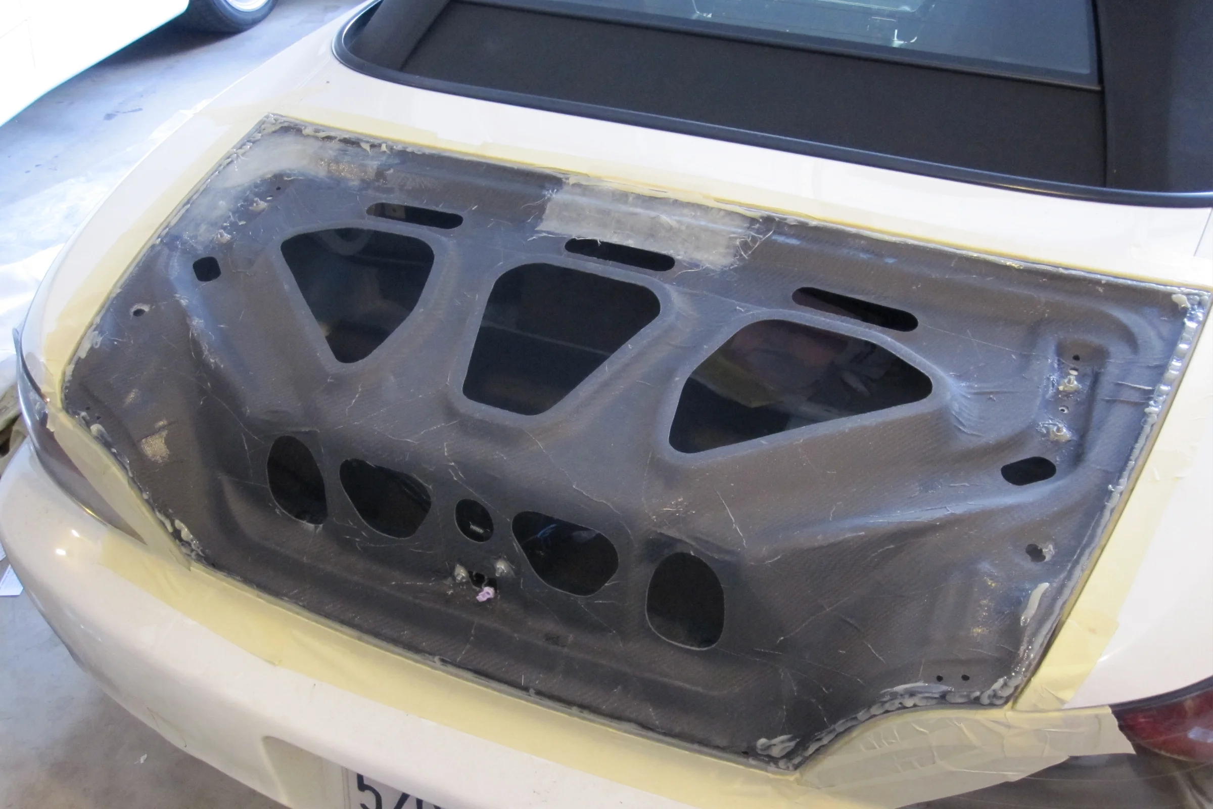
Bonding the skin to the skeleton frame was done with the skeleton bolted to the car and the trunk in closed position, so all four panel gaps could be set simultaneously. Business cards were used as shim stacks at every critical gap point, add a card to close the gap, remove one to open it, until all four edges matched the factory panel gap exactly. Cured in place. Shell weight: 1.77 lb. With trunk latch, third brake light, and all mounting hardware: under 3 lb. OEM steel trunk with hardware: approximately 18 lb.
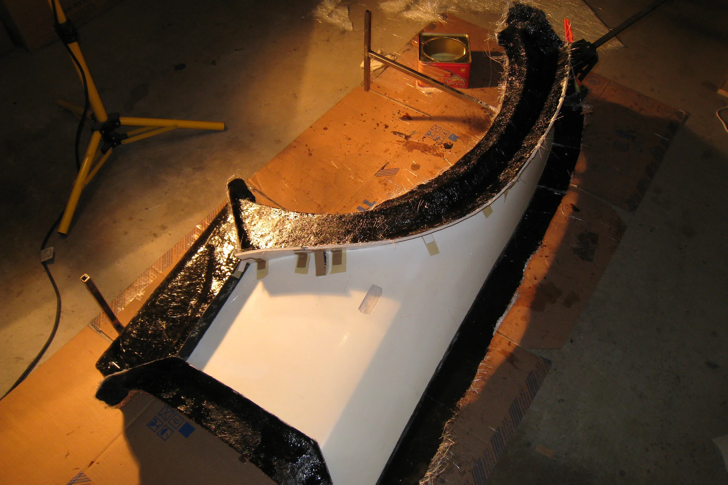
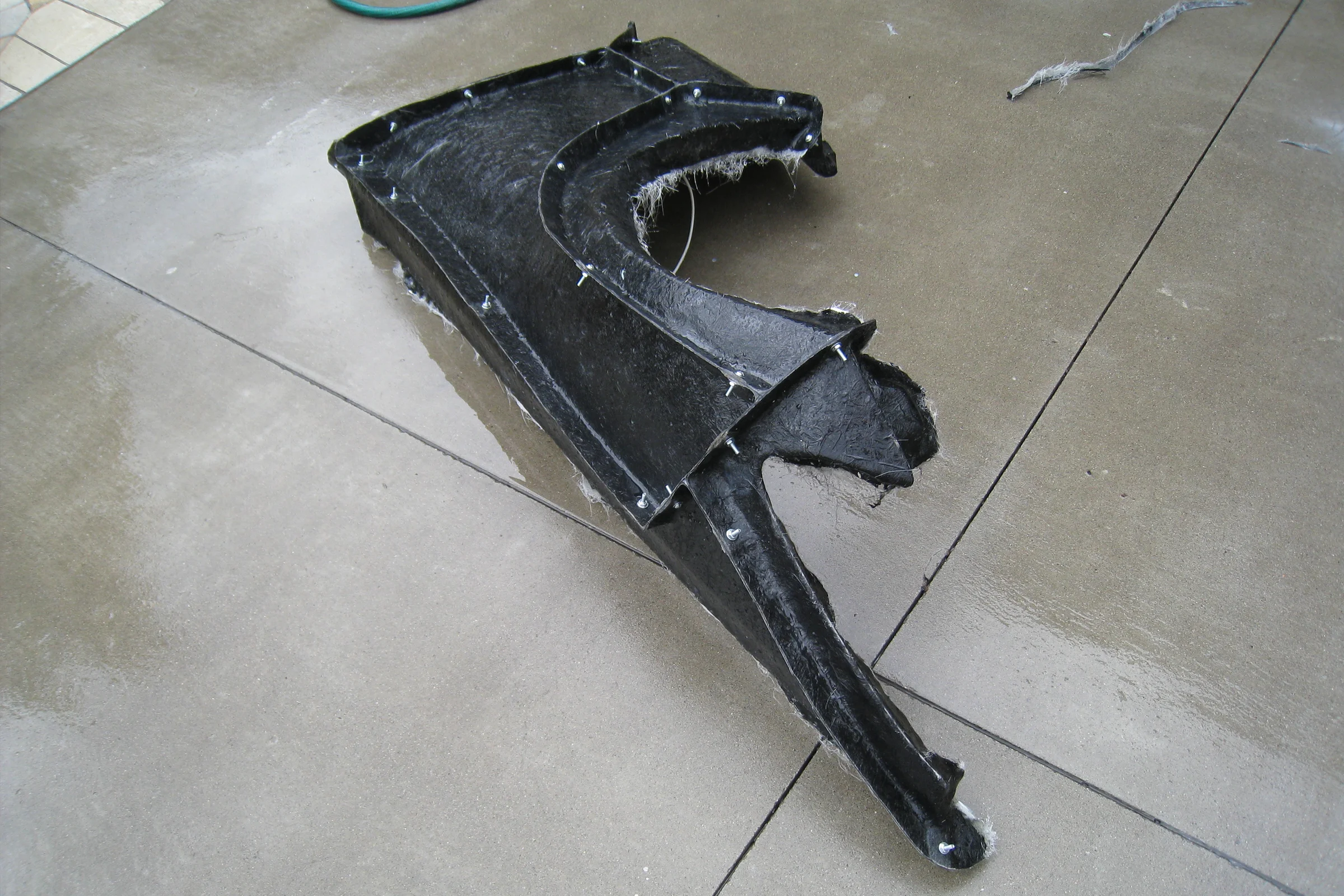
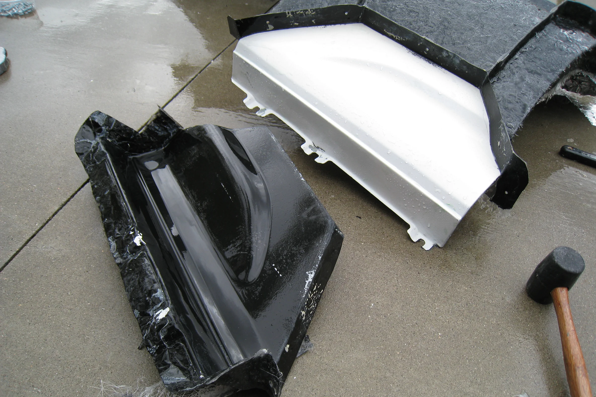
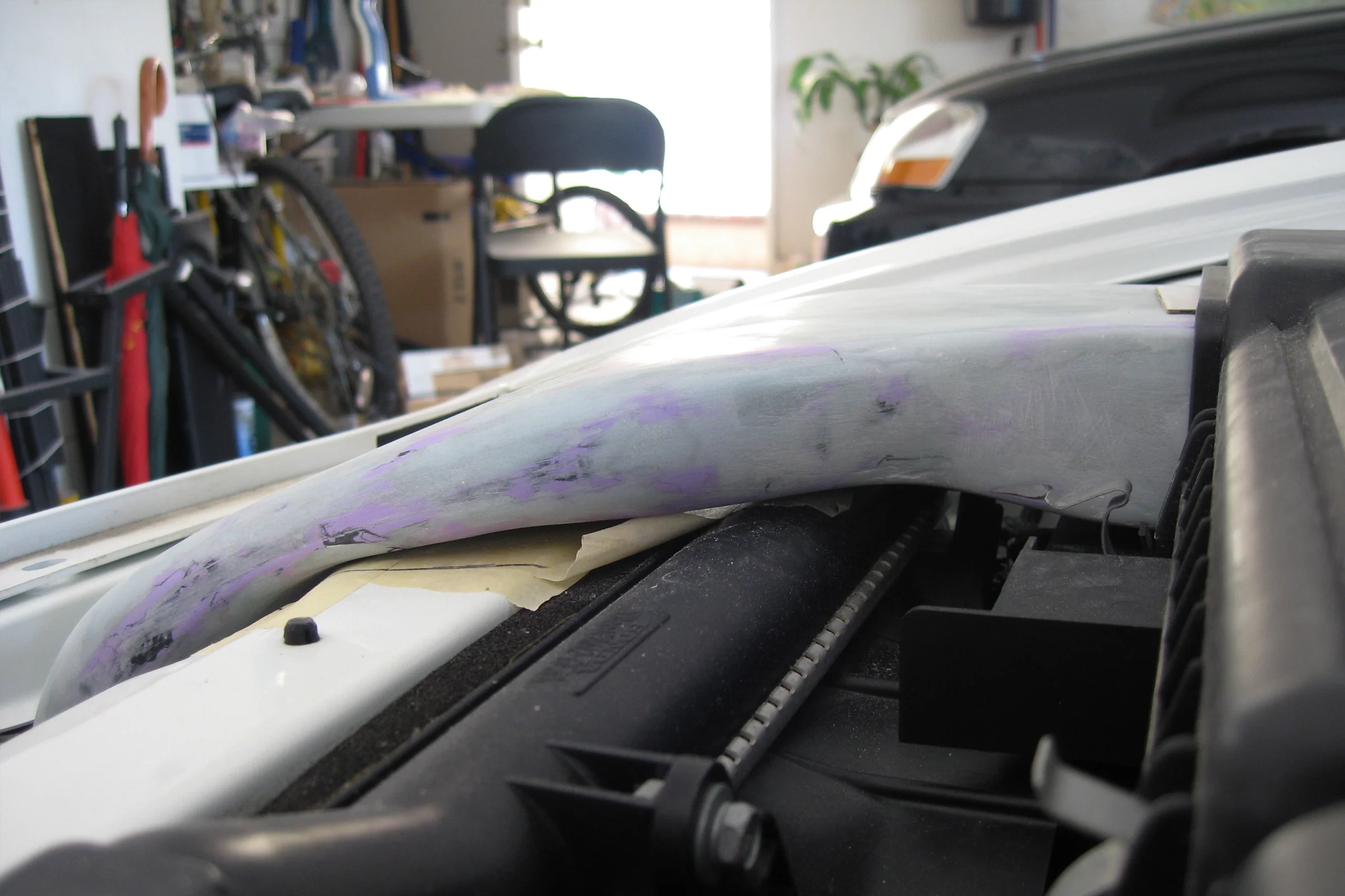
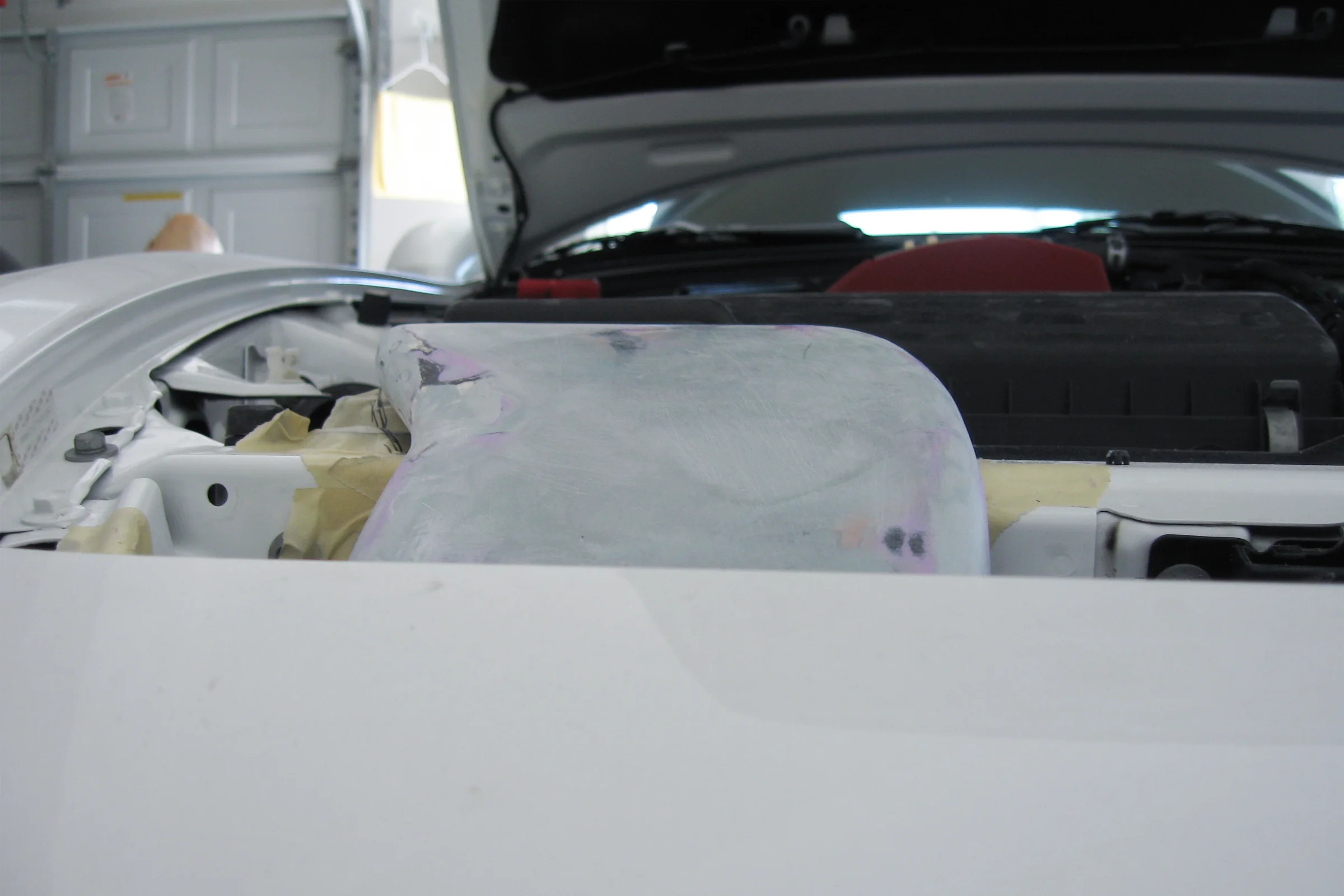
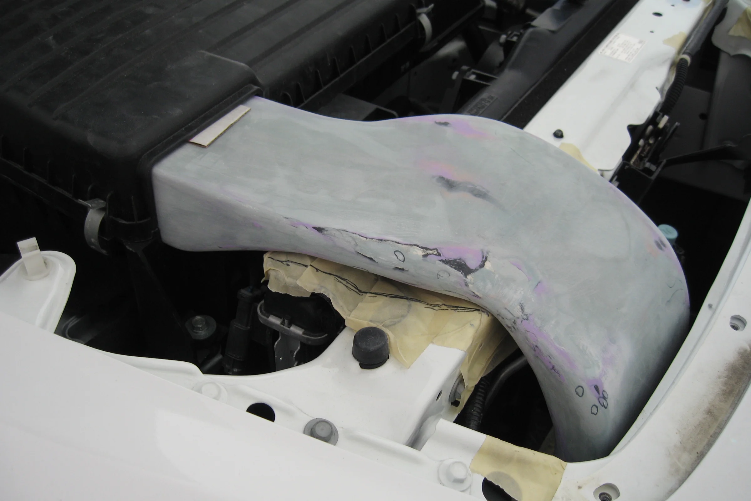
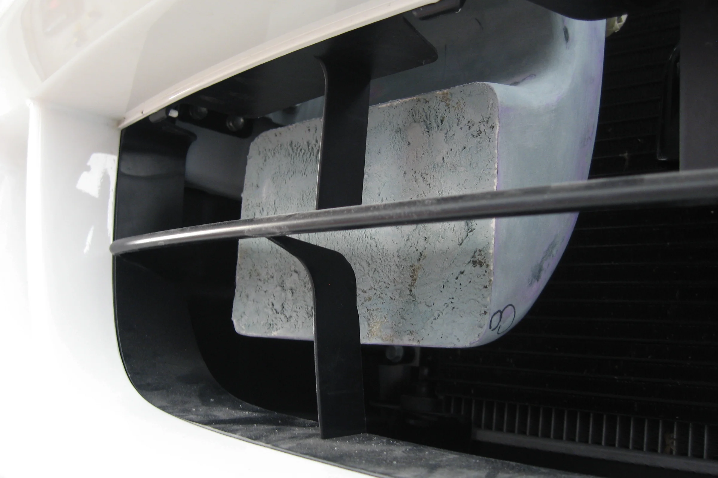
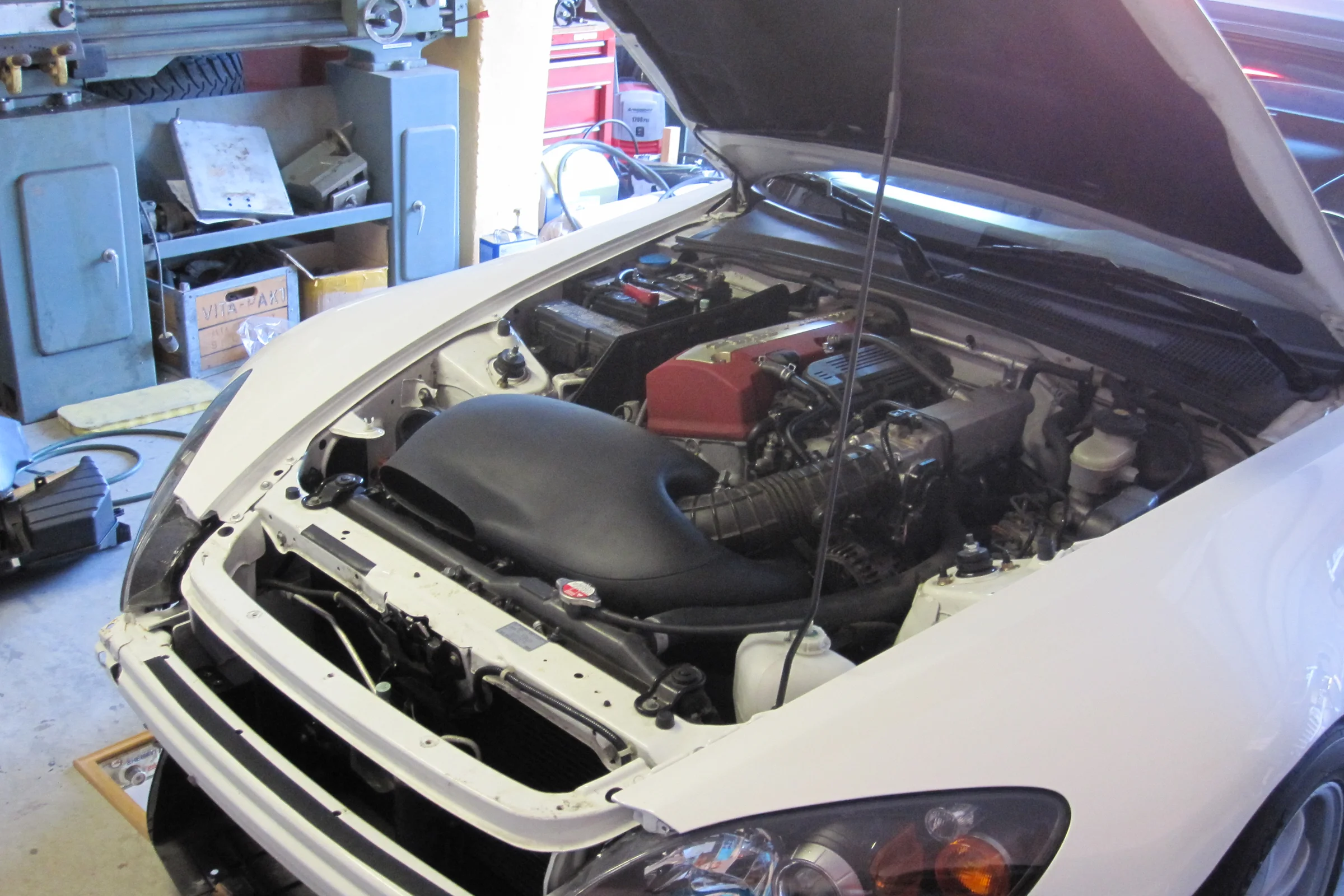
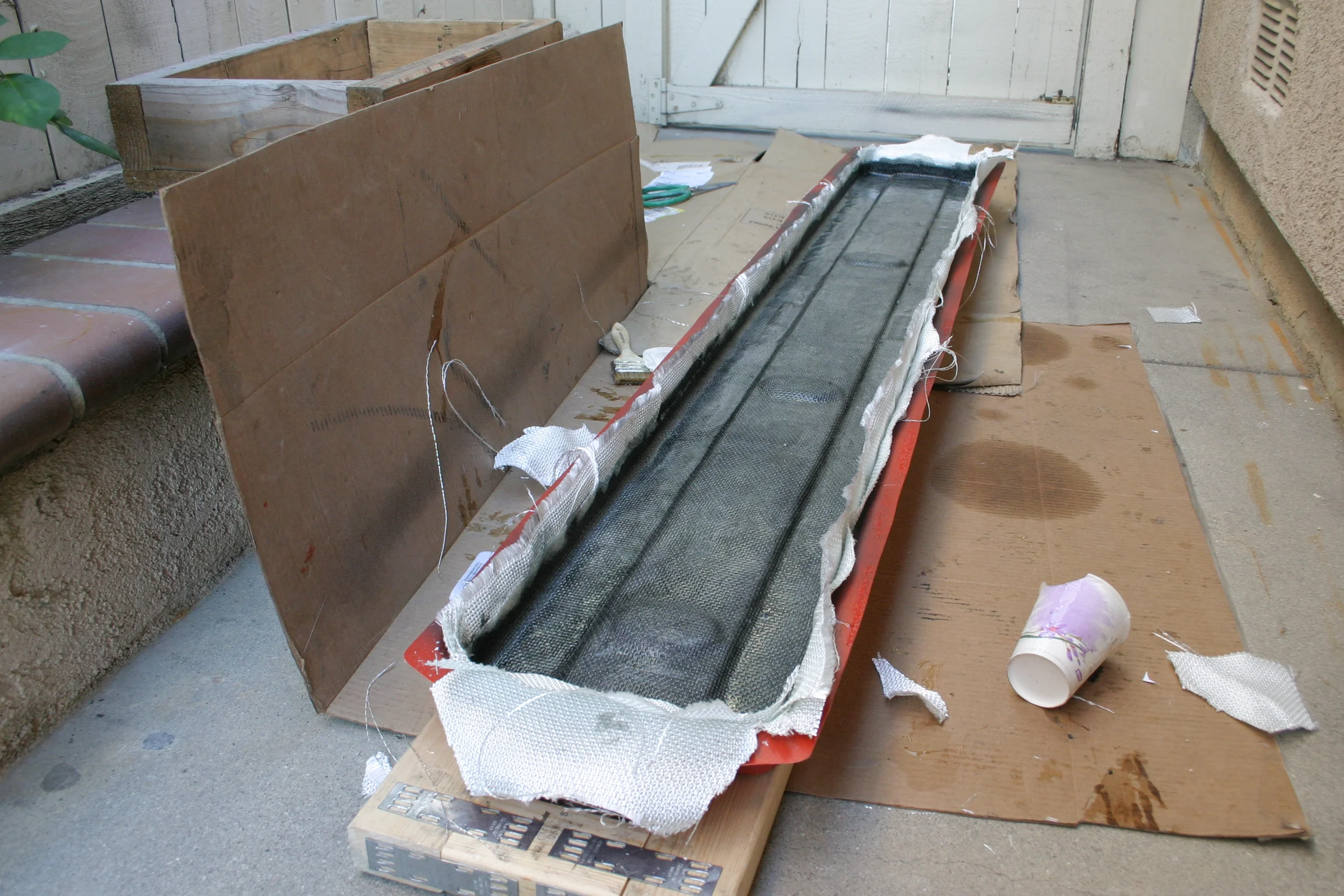
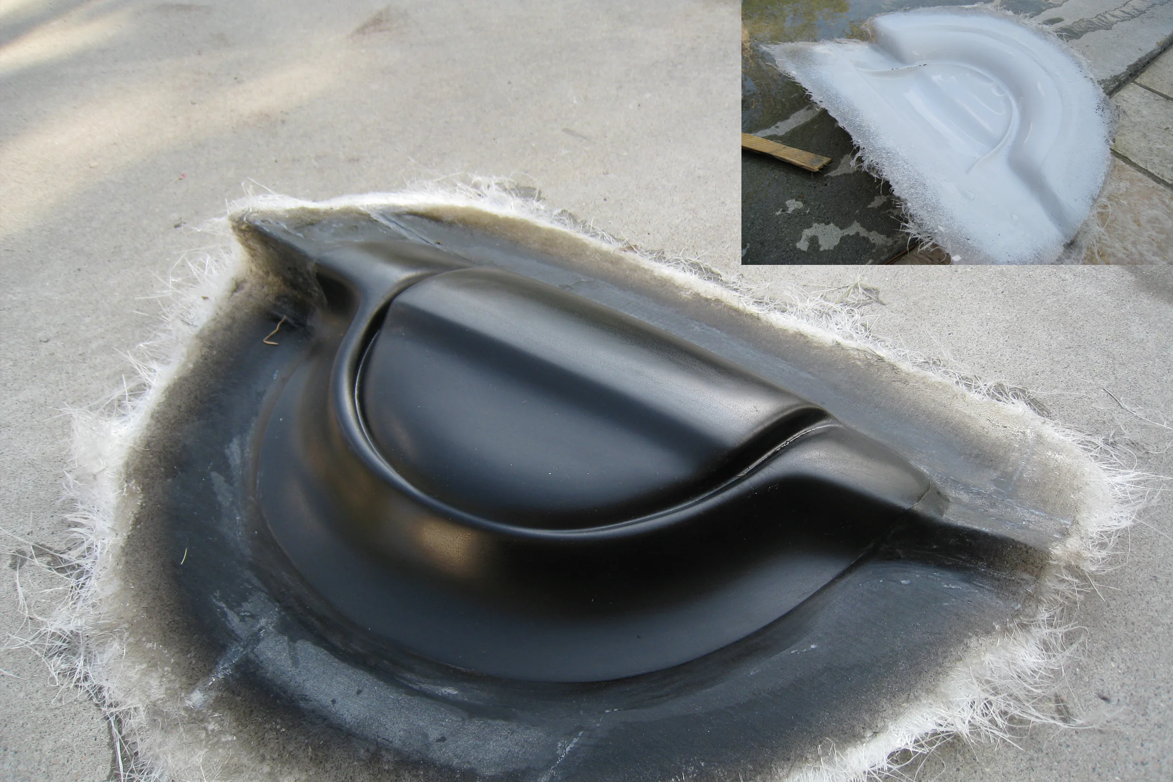
Composite Intake Snorkel, Hollow Structure from Scratch
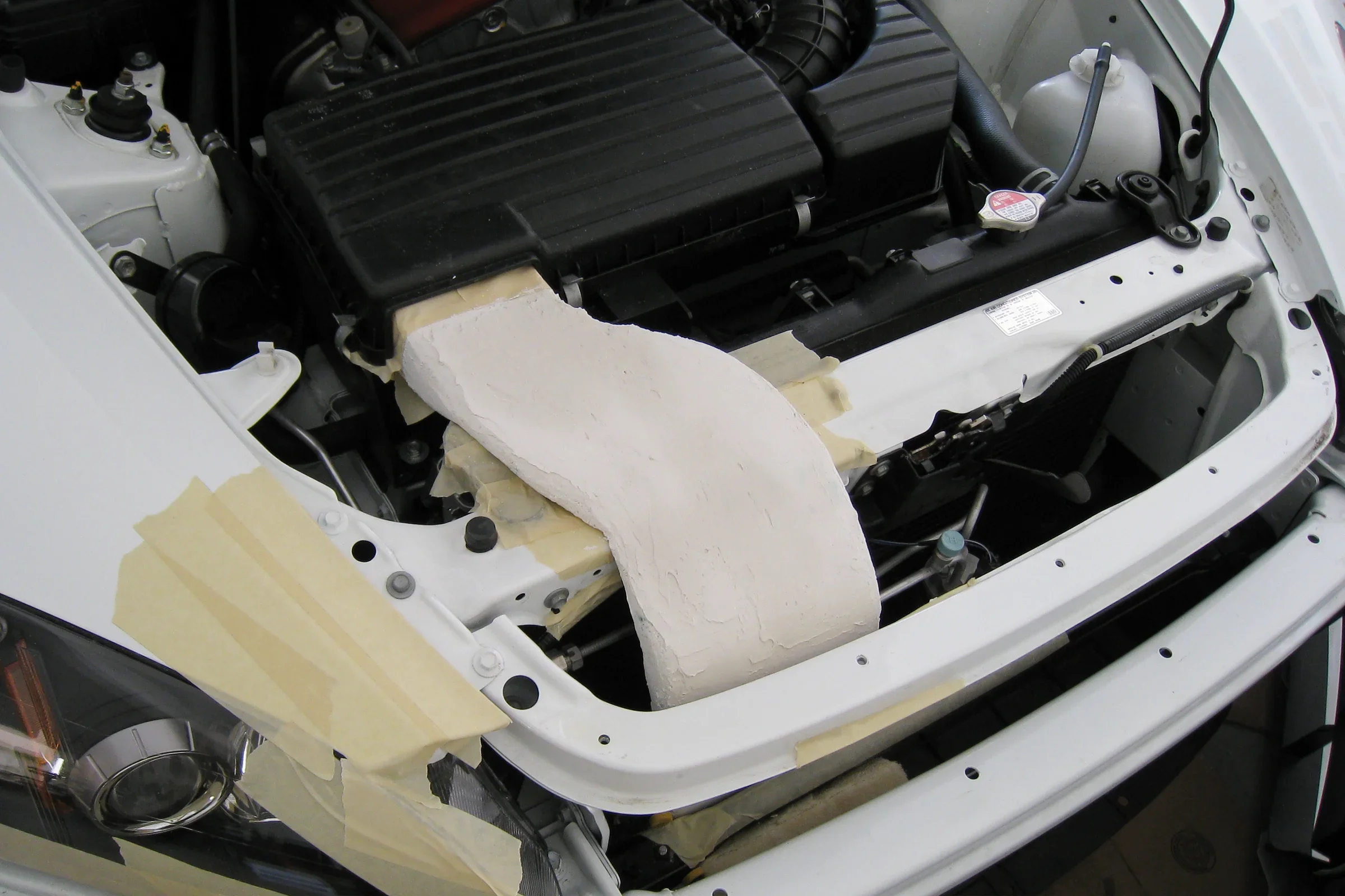
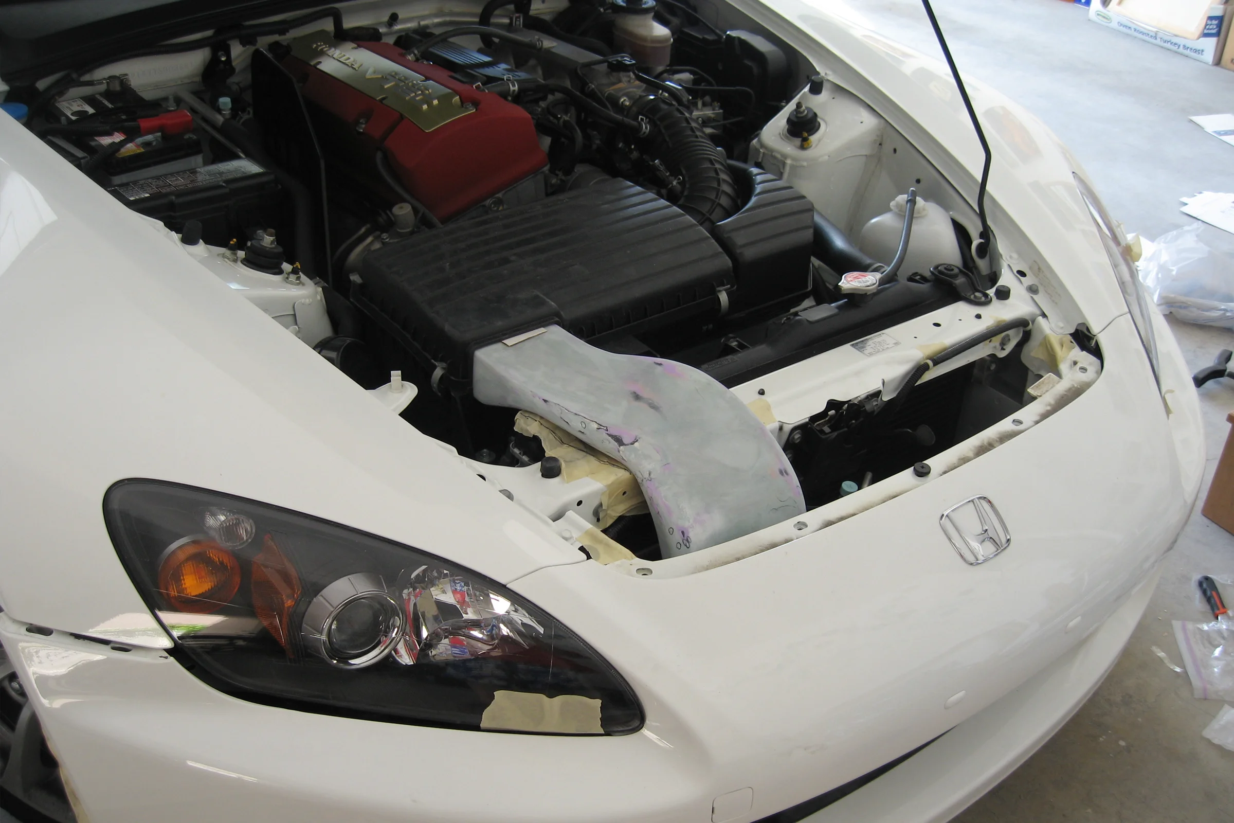
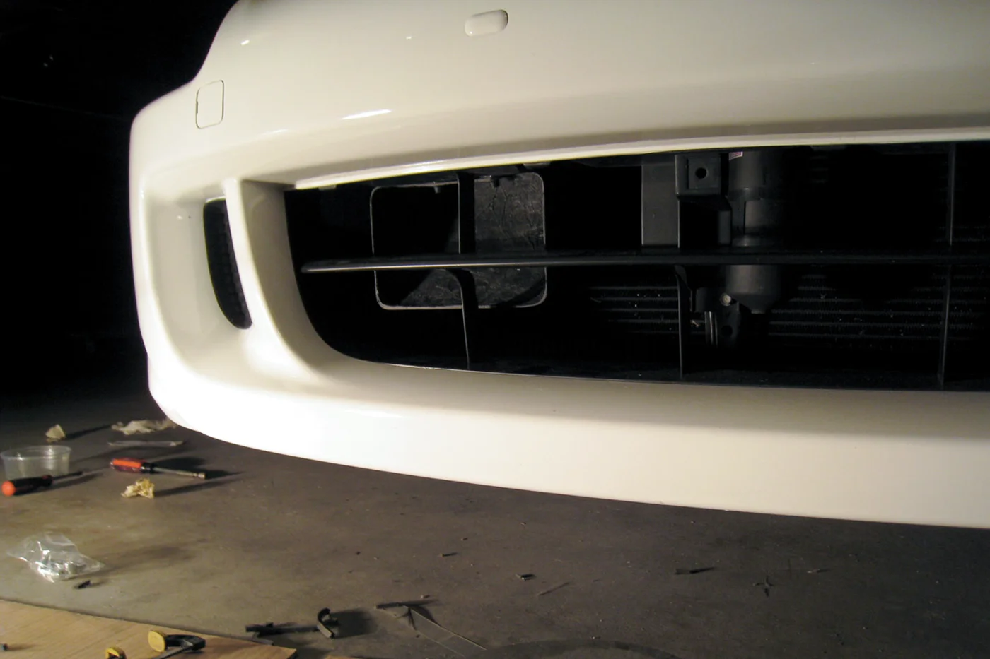
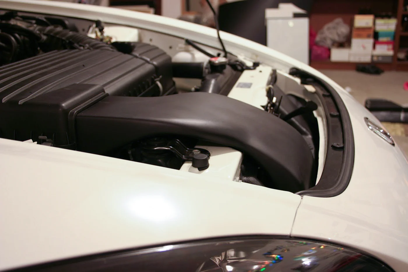
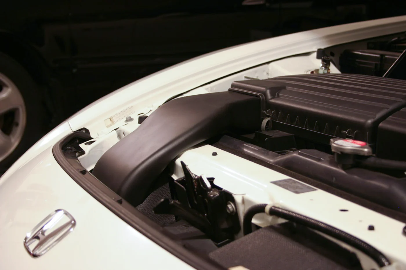
Honda's engineers left a clue: the underside of the factory hood has an indentation shaped like an air path, positioned directly above the radiator support at the tightest pinch point in the engine bay. The intake airbox horn almost lines up with it. For reasons that were almost certainly water ingestion liability, a factory snorkel never made it into production. Every aftermarket option that existed required cutting that pinch area, a large hole in the hood structure, to fit a bulkier fiberglass tube. That was unacceptable.
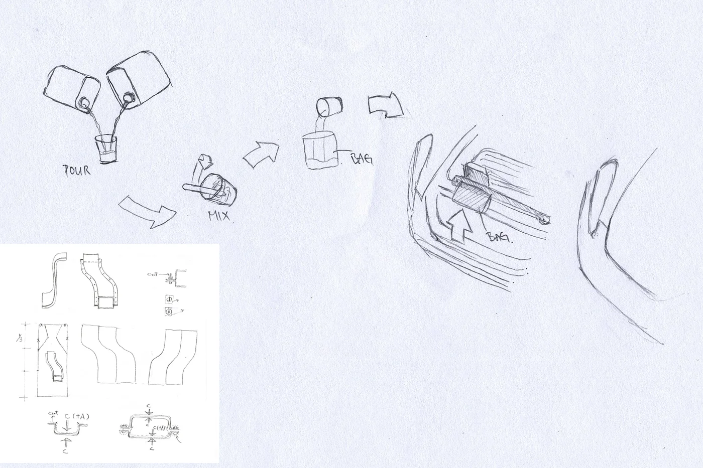
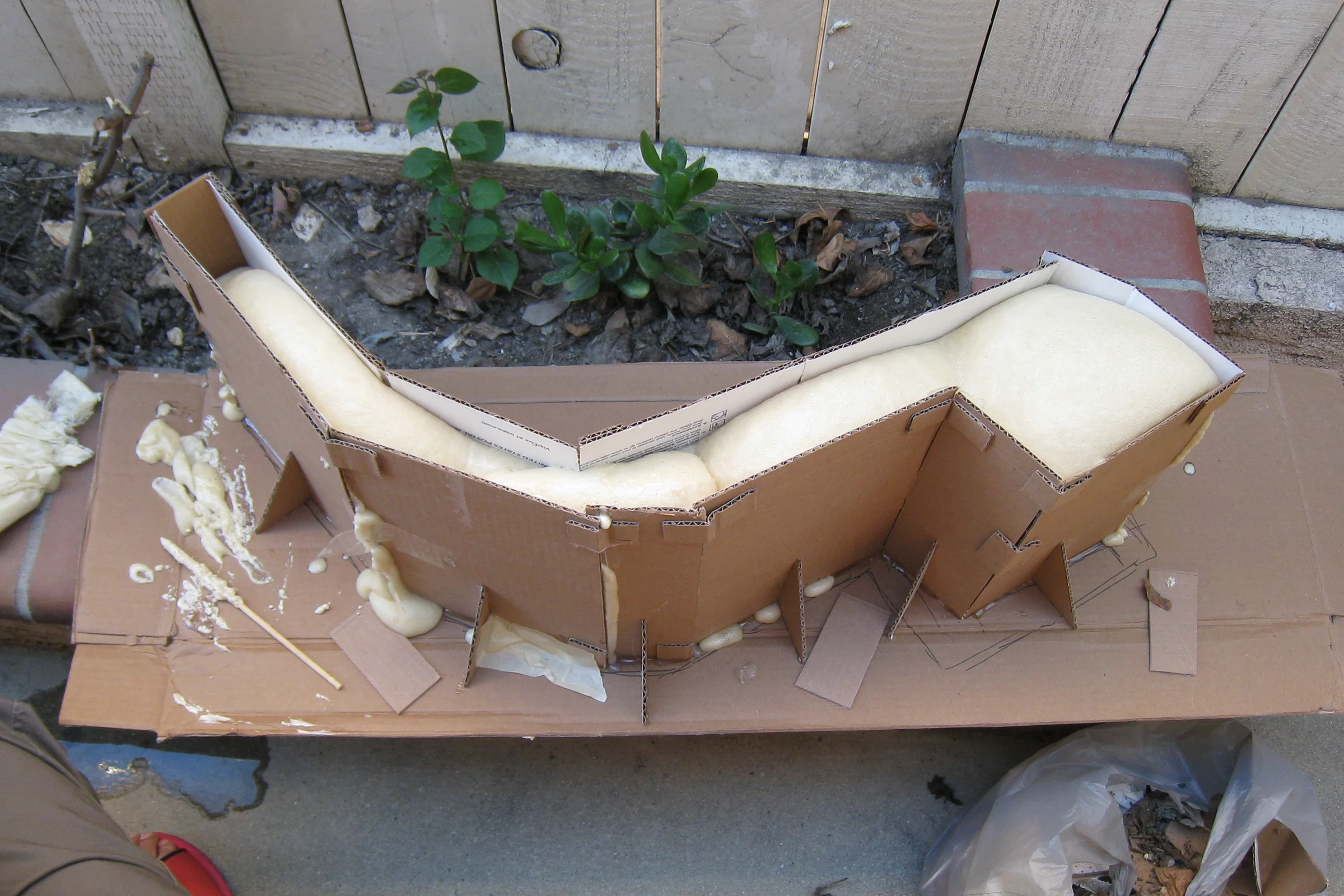
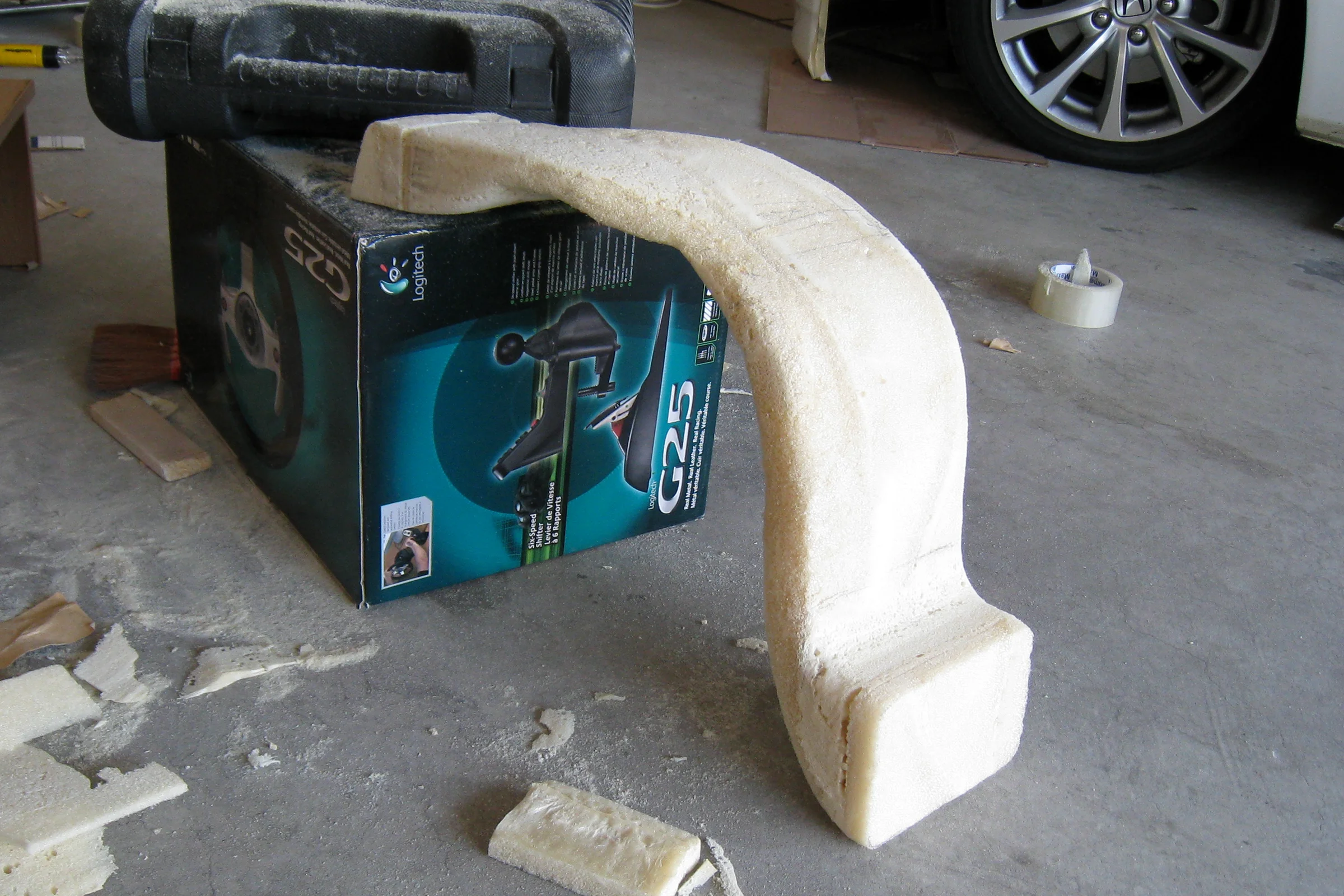
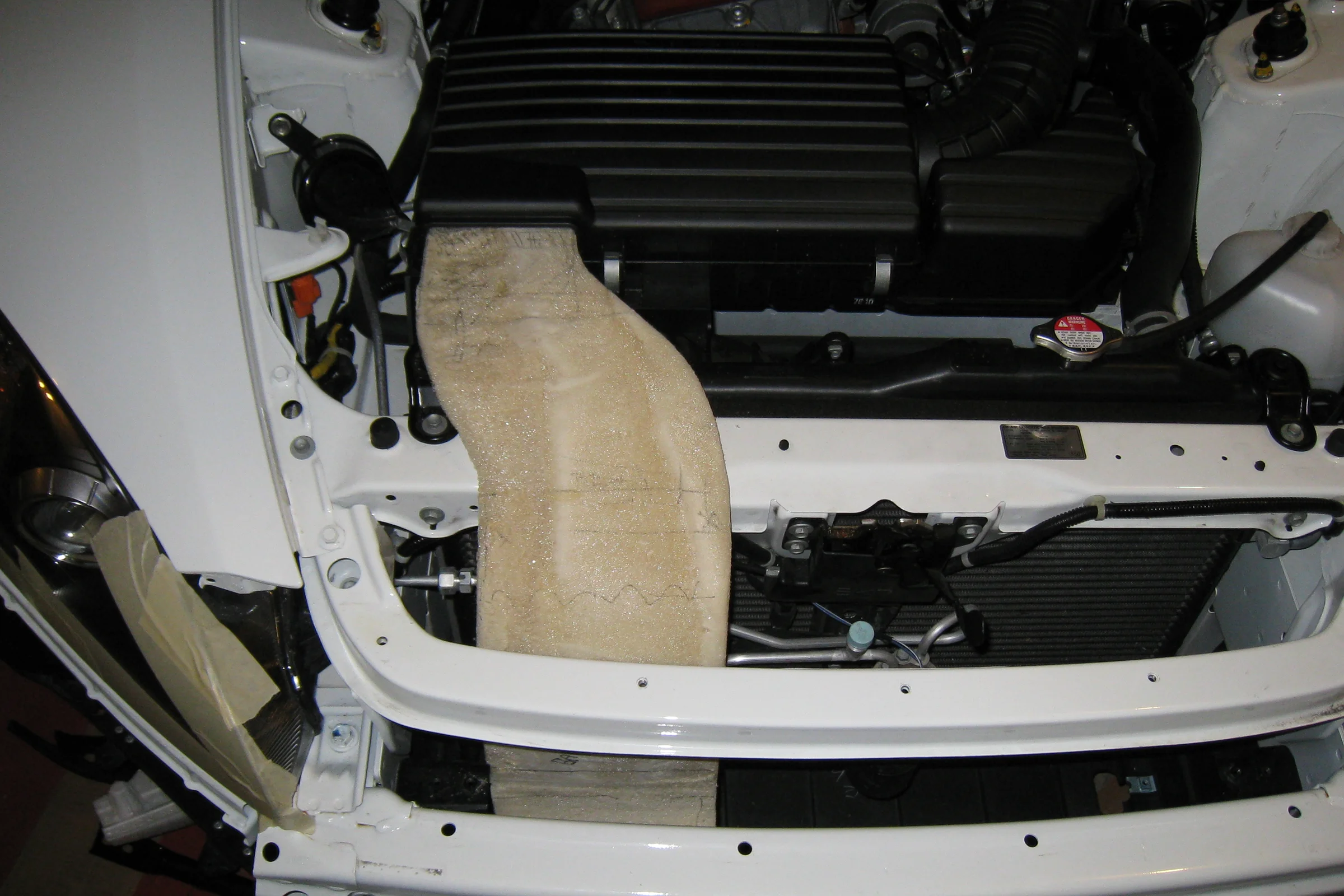
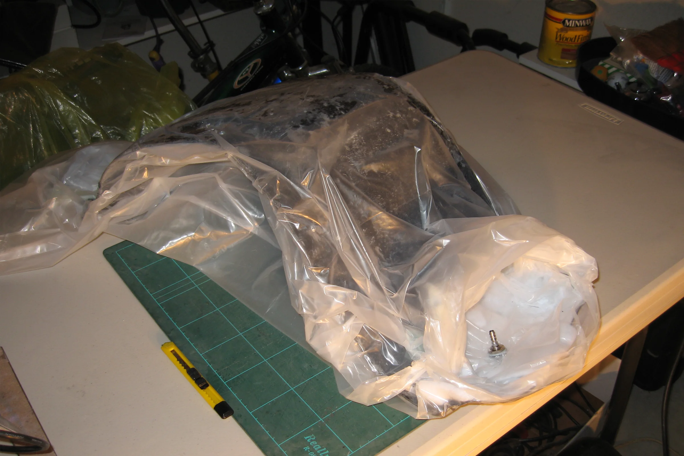
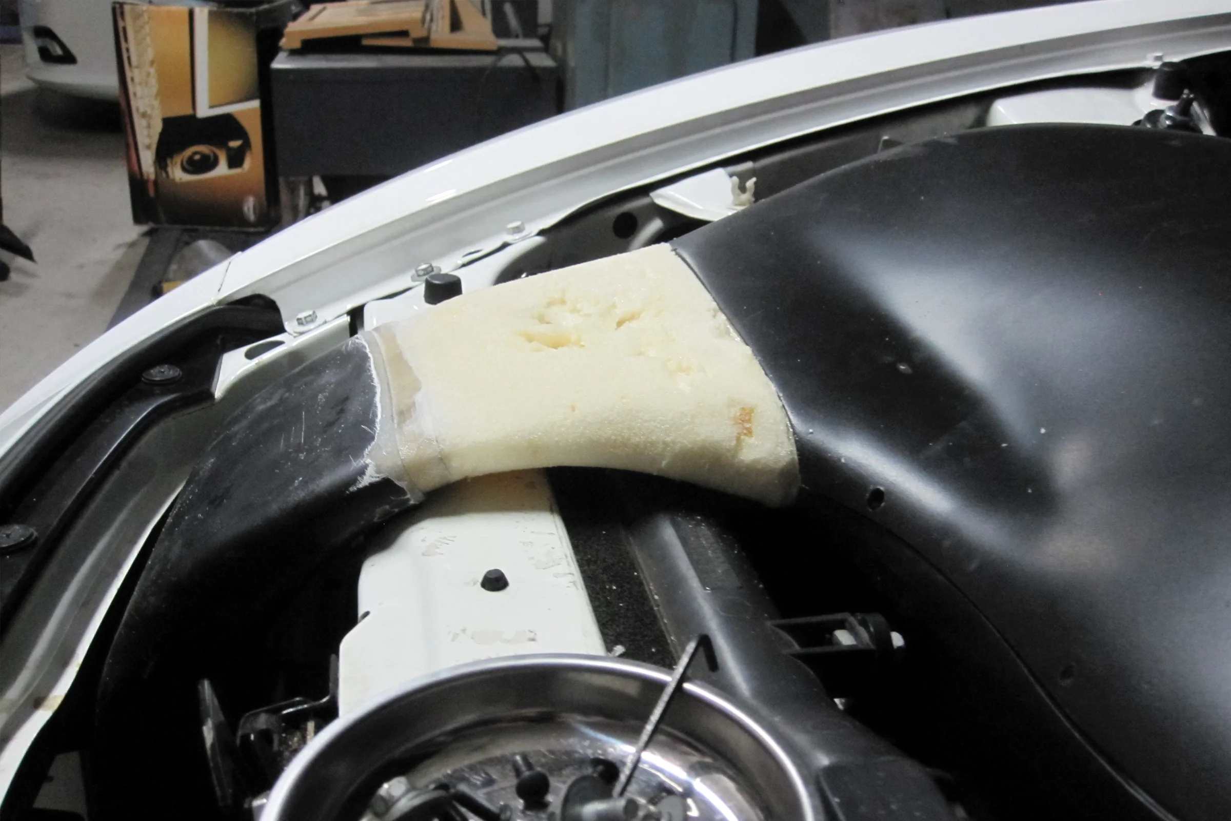
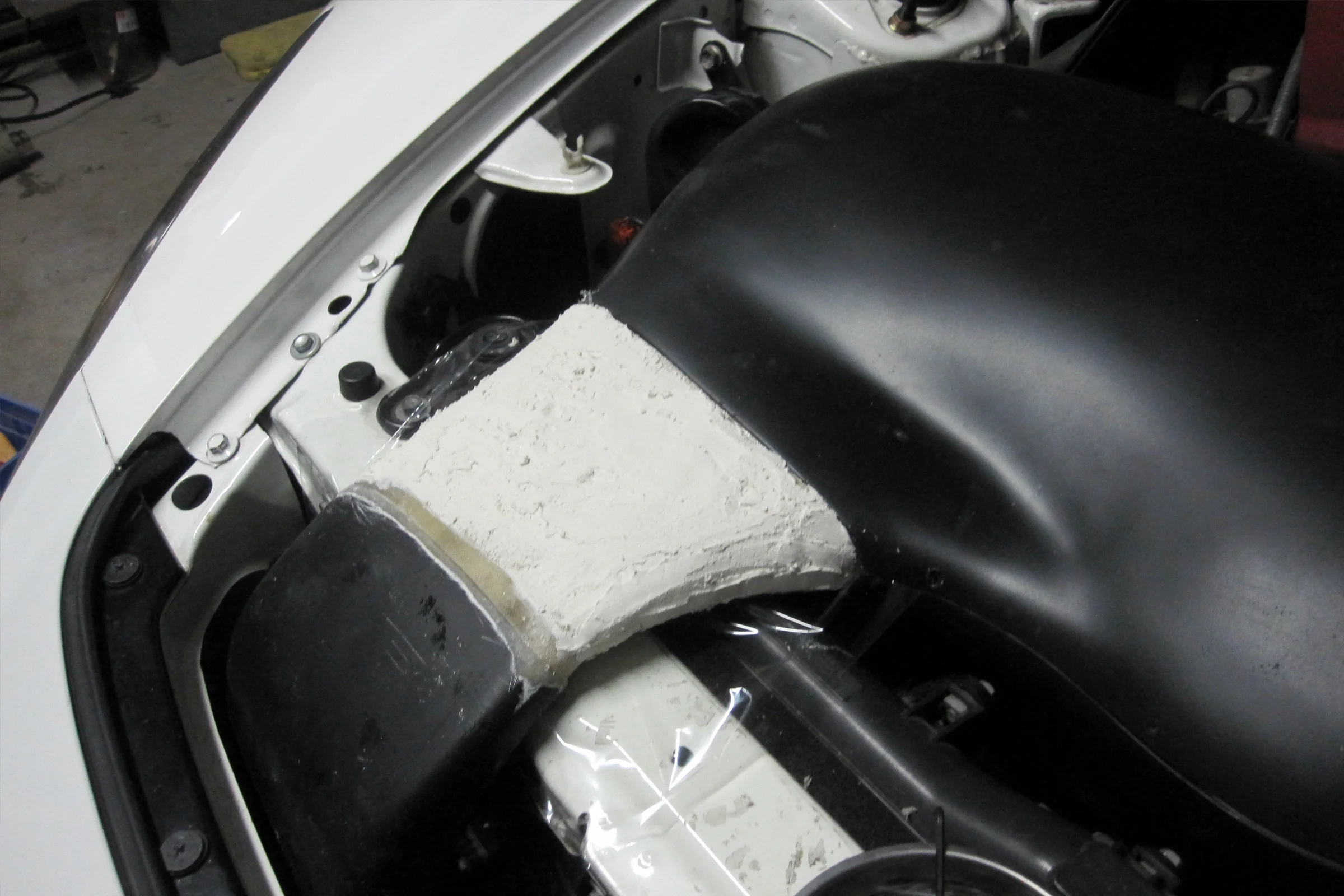
Before designing anything, the constraint had to be physically mapped. A Ziploc bag was filled with polyurethane expanding foam and placed at the pinch point between hood and radiator support before closing the hood, sealing the bag to contain the expansion, letting it cure into the available geometry, then pulling it out. That gave a physical read on the critical width. From there, a full-size cardboard mold of the snorkel footprint was built and filled with foam, then shaped by hand until it sat cleanly under the closed hood at the tightest point. The same constraint-first methodology as the Hunter Douglas rescue, applied to automotive packaging. What the foam model made immediately clear was that the pinch point wasn't a flow bottleneck if you traded height for width: a flattened, laterally wider cross-section at the tightest point maintained the same flow area as the rest of the snorkel path. Consistent cross-section throughout, no cuts to the hood structure.
Learning composites from scratch presented its own problem: there was almost no useful information available at the time. Searched Google Maps for "fiberglass," called every result, and eventually found a family-owned boat repair yard near the coast with a small storefront selling to surfers and small-boat builders. The yard rotated its repairmen through the front counter, which meant every visit was a chance to show work, describe failures, and get direct feedback from people who built things with composites professionally. That shop became an informal development partner for the first year of composites work.
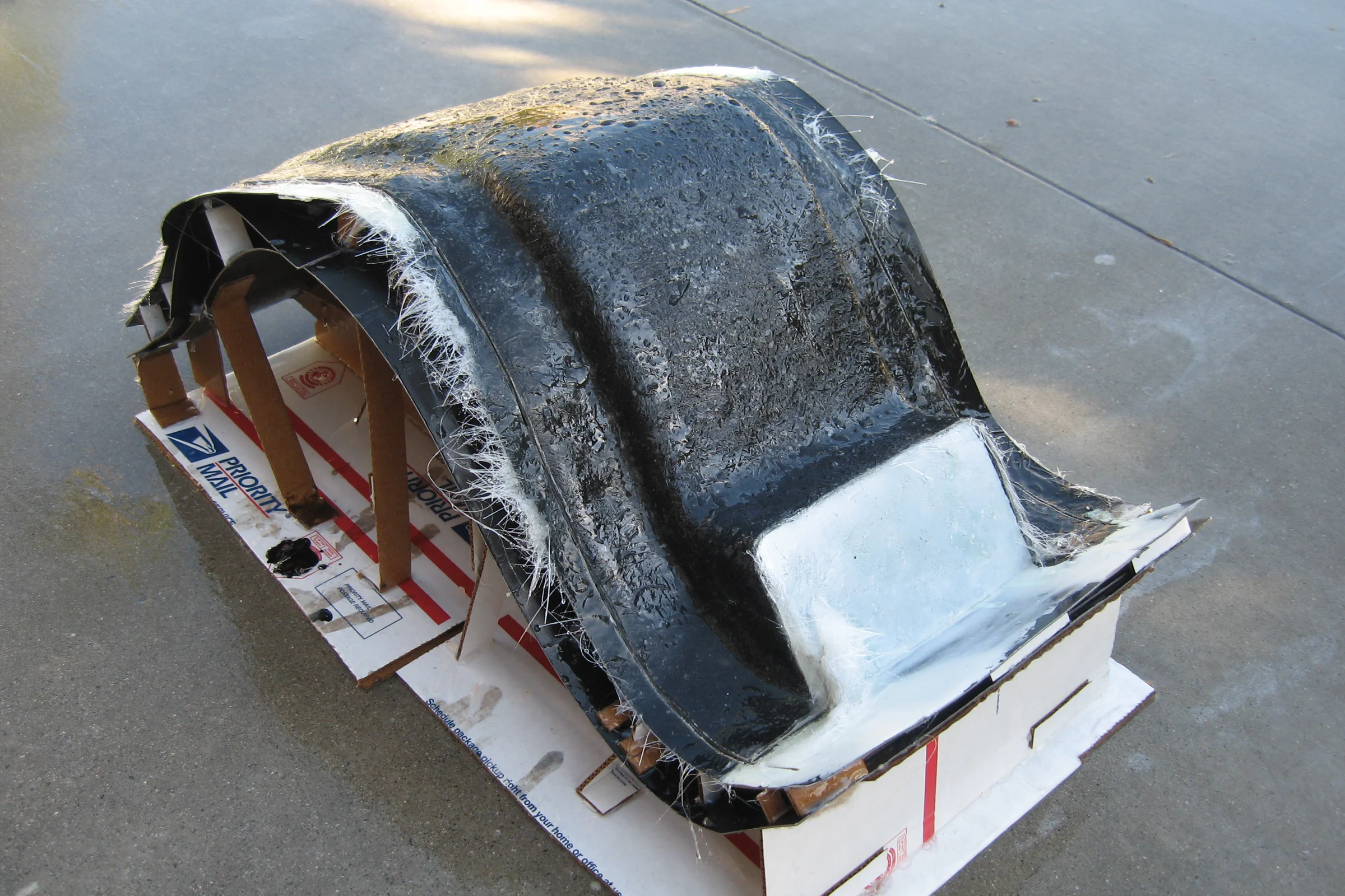
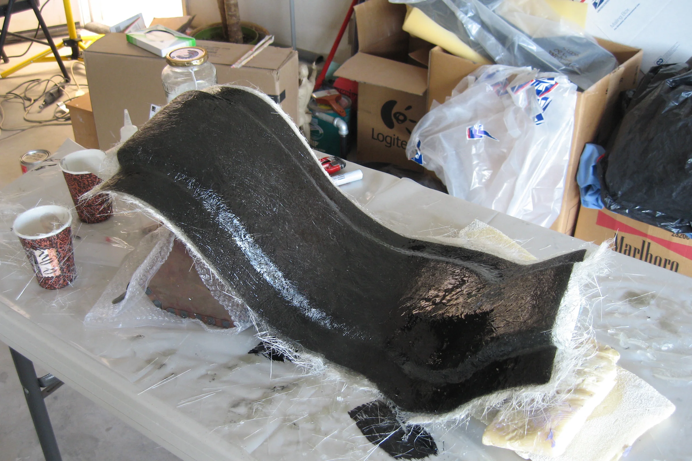
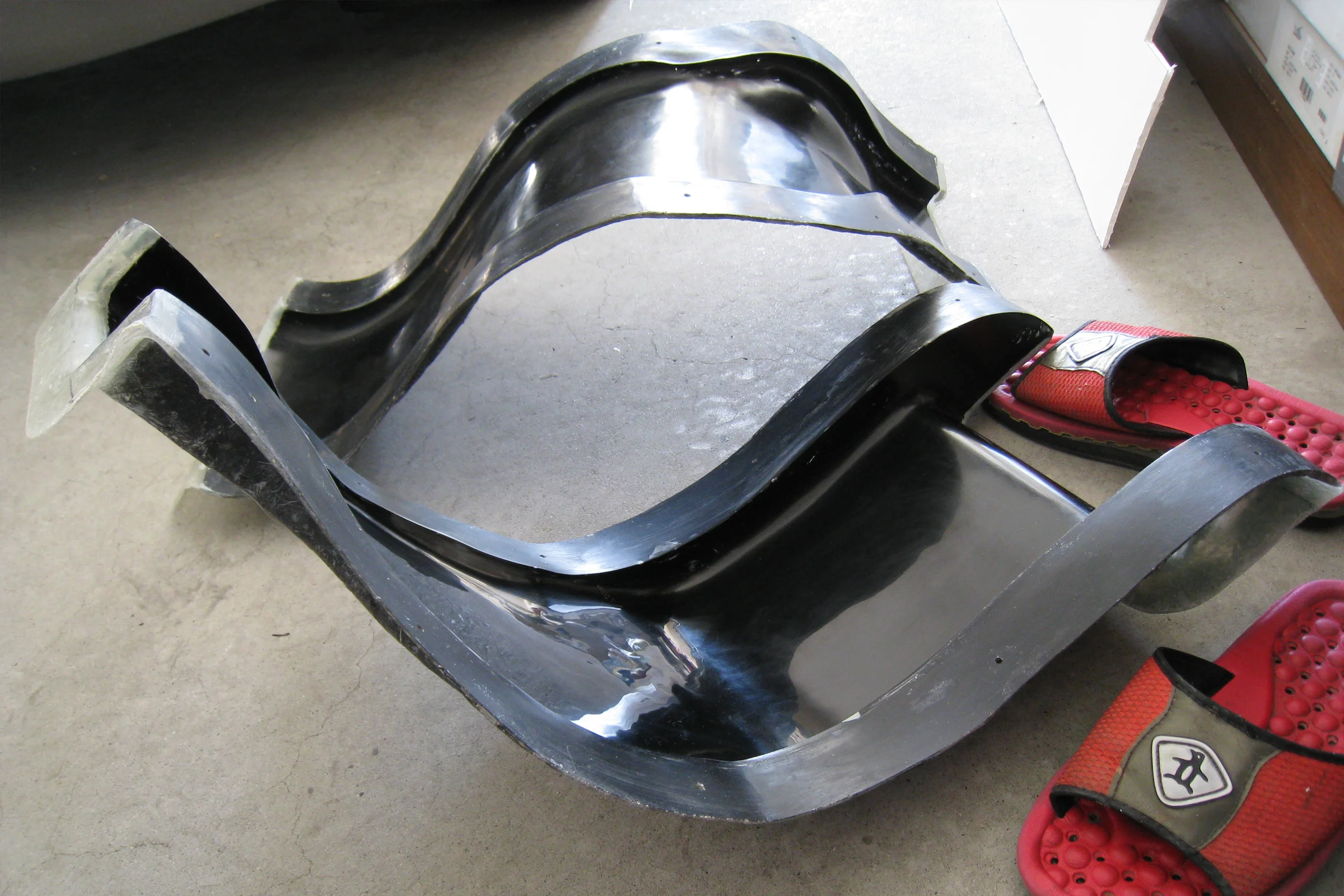
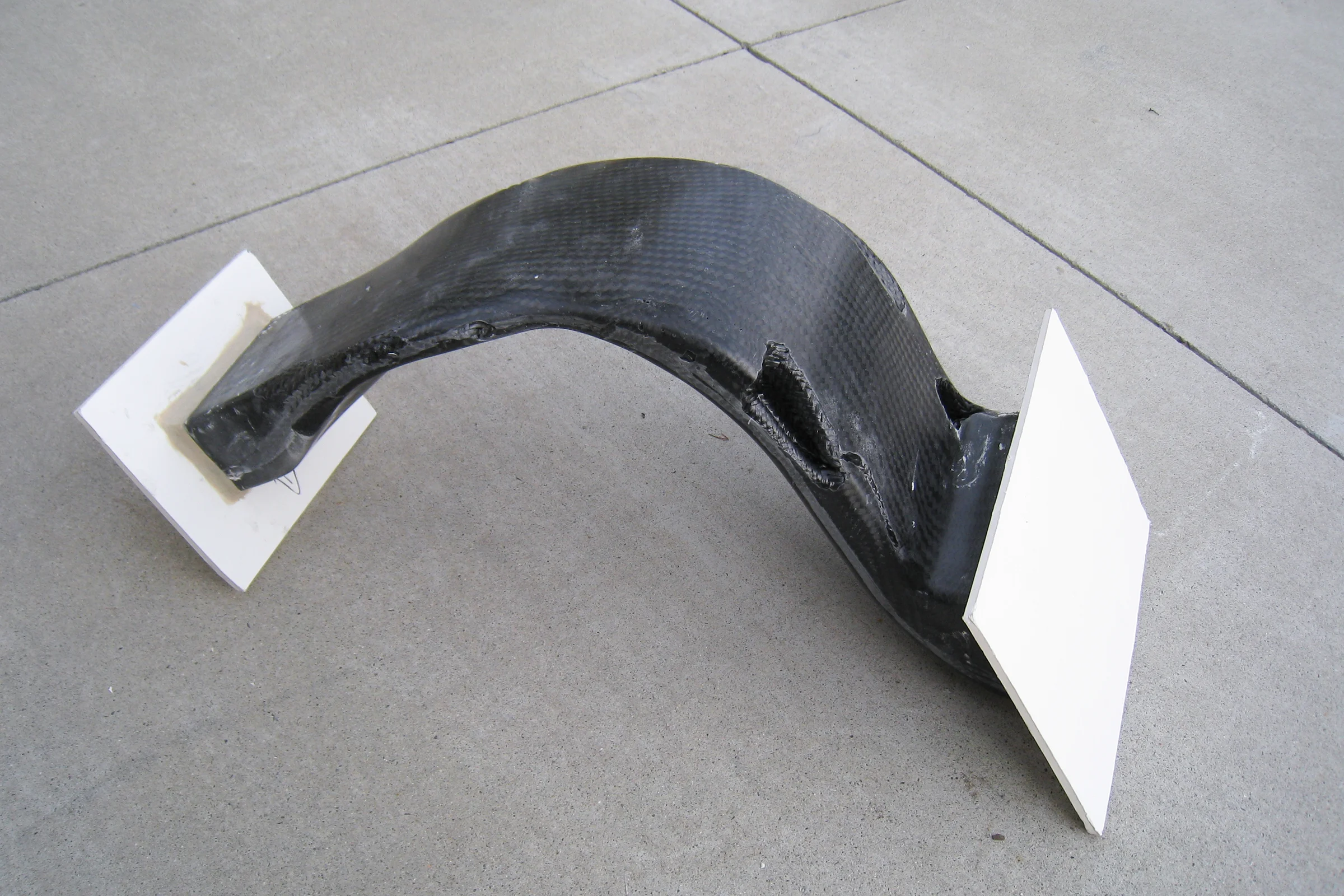
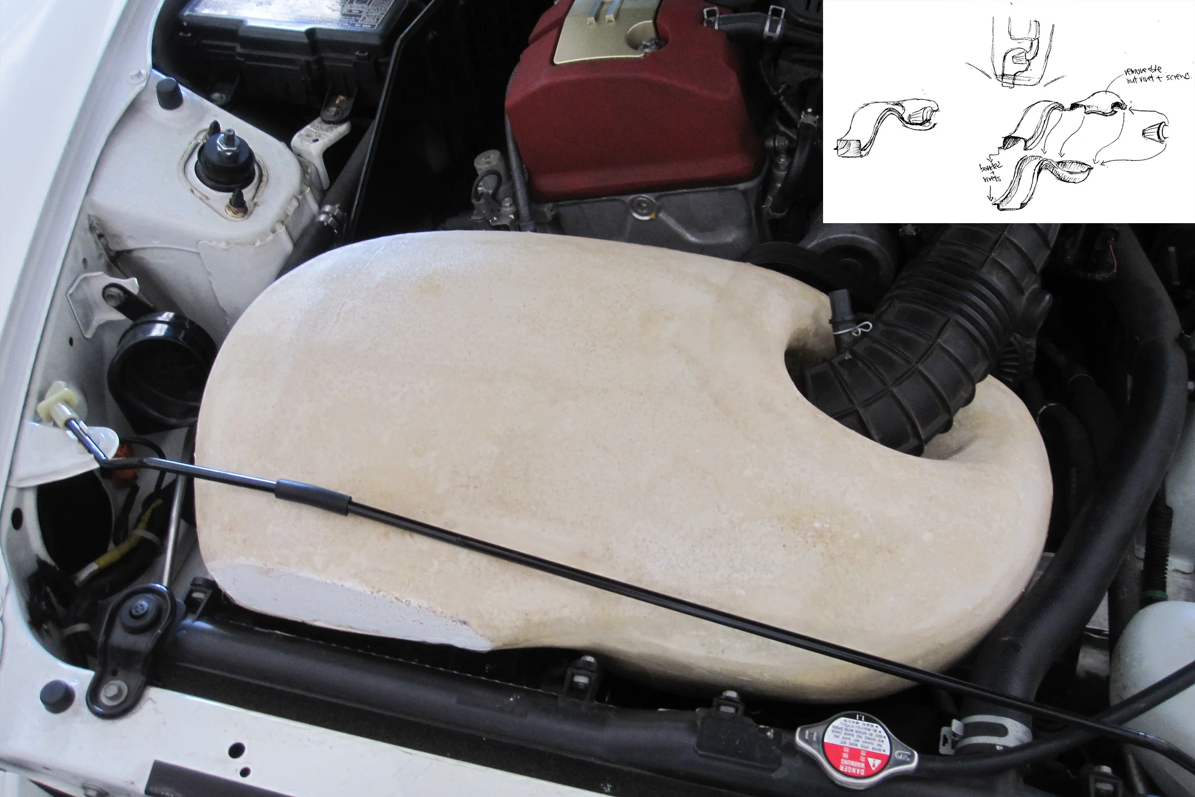
The intake snorkel was a deliberately difficult first project: long, thin, S-curved, and hollow. Most composite parts are solid or open-faced. A closed hollow tube requires continuous layup through the interior with no access once the mold closes. The first attempt used a pre-woven carbon fiber tube, the theory was that vacuum-bagging it against the inside of the mold, with the bag wrapping the entire closed mold in a donut shape, would press the tube uniformly against the surface. In practice the tube didn't have enough stretch to conform to the mold geometry. Expensive and documented failure. The vacuum pump at this stage was a bicycle pump modified to pull vacuum in reverse with a check valve inline, the refrigerator compressor conversion came later.
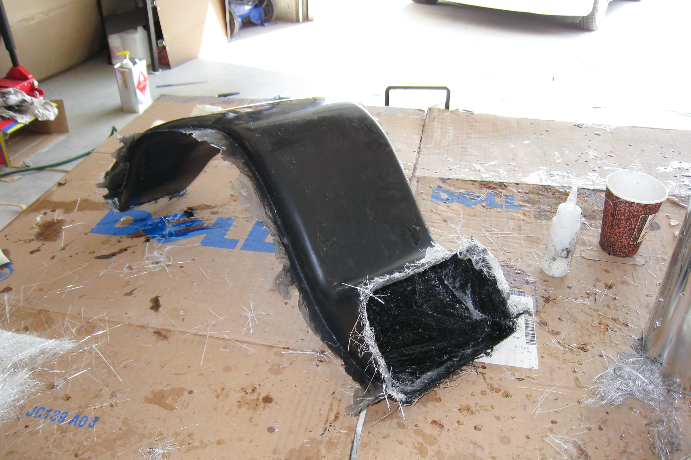
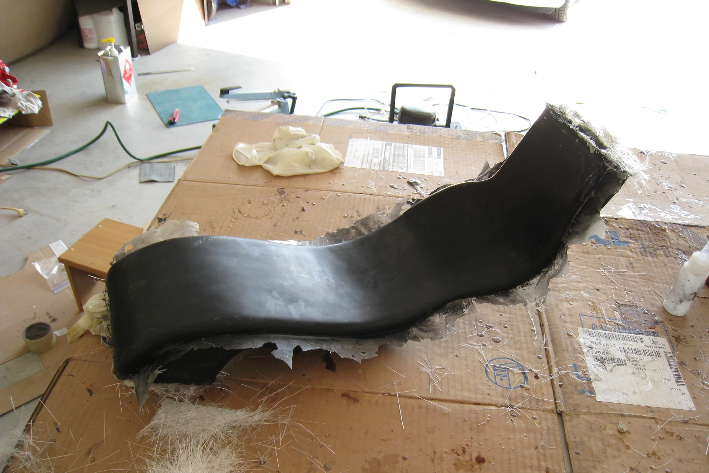
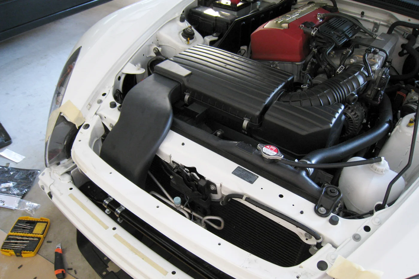
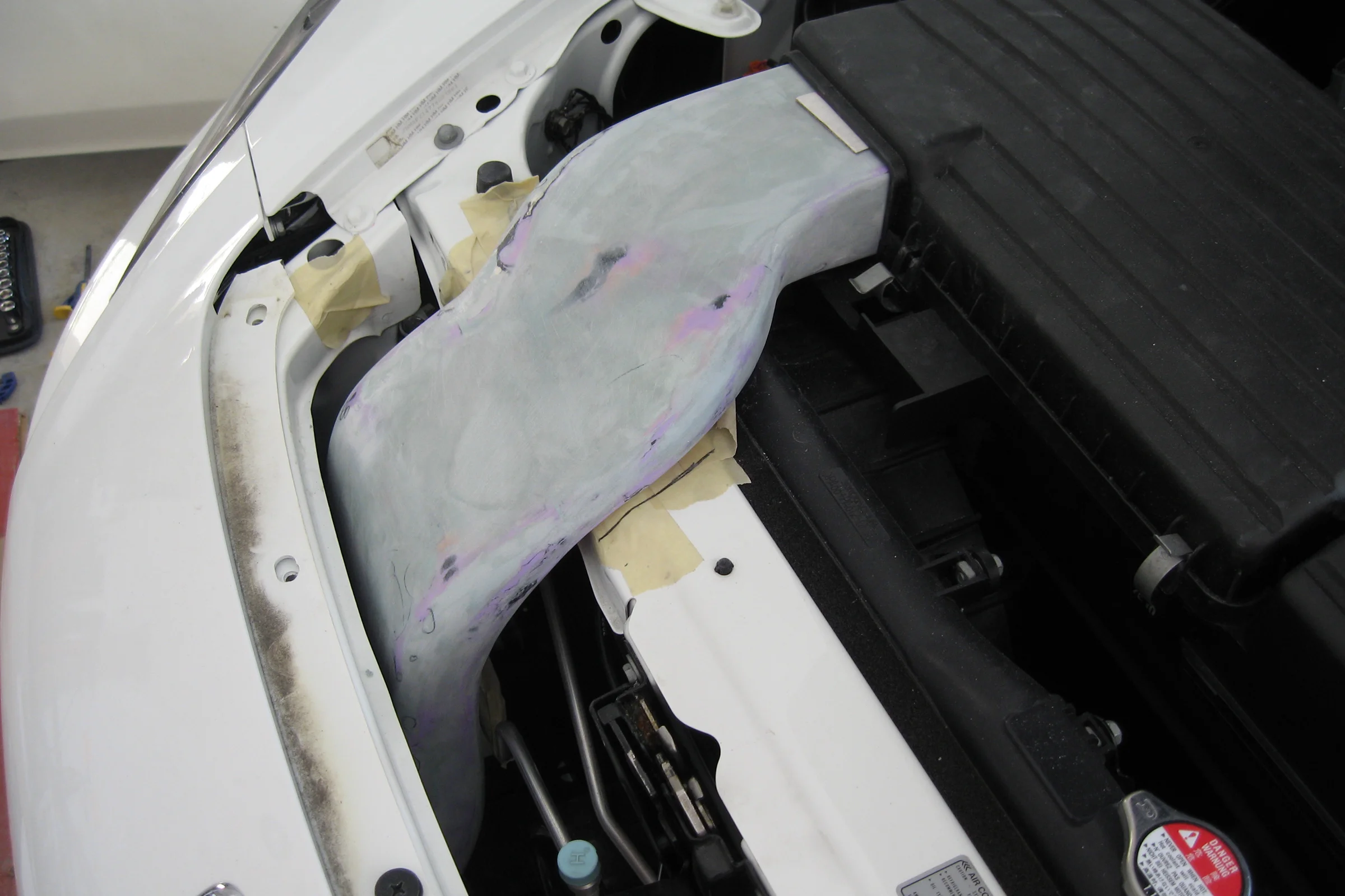
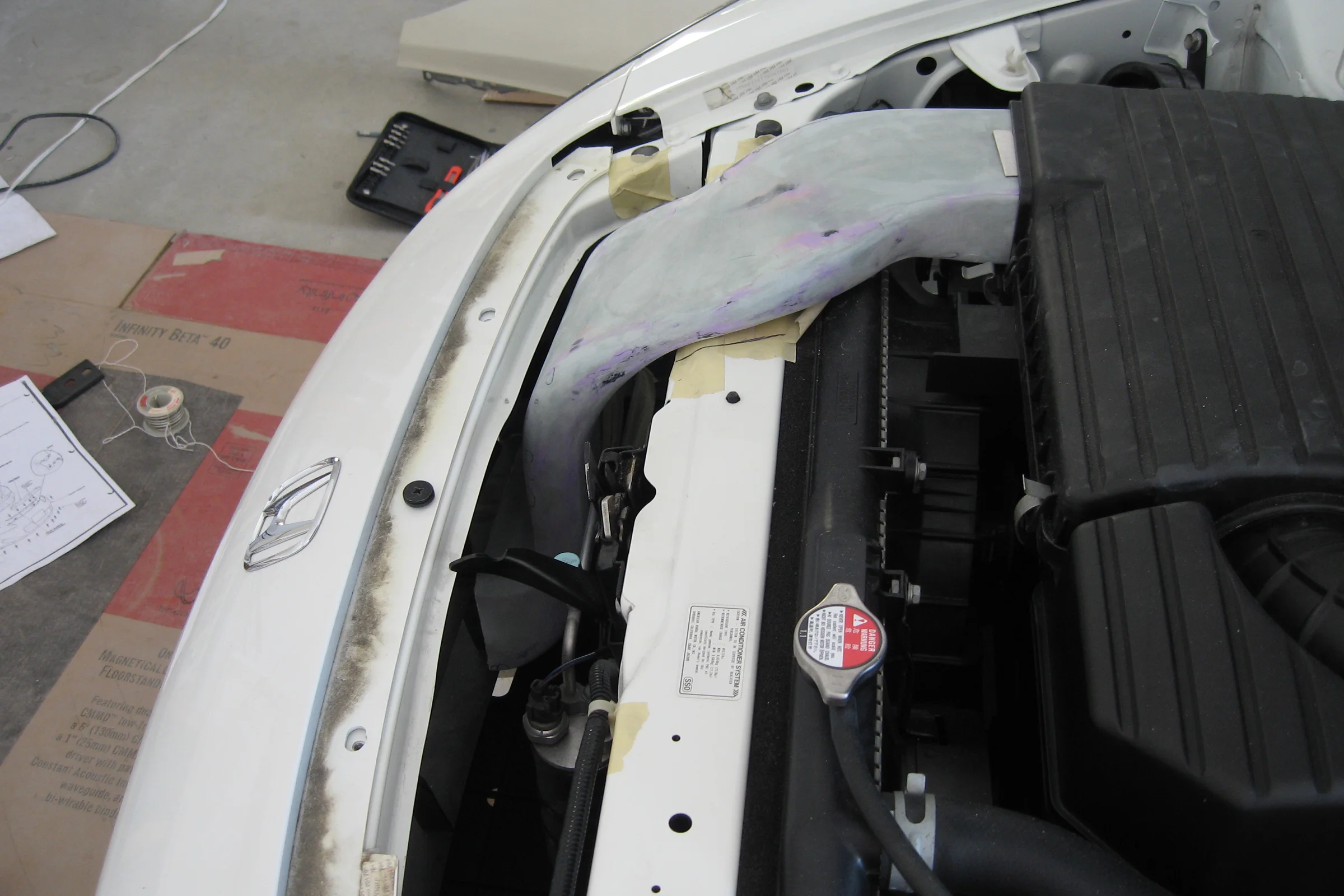
The method that eventually worked was hand-laid fiberglass on both mold halves with a plastic-sheet inflatable bladder placed inside before closing, inflated after the mold bolted shut to press the wet layup against the surface while curing. That produced an 80-percent result on the first attempt, close enough to test-fit for hood clearance. Multiple further iterations got it to a production-ready geometry. The engineering boundary drawn from the start: nothing after the intake filter could be DIY composite. Any failure upstream gets stopped by the filter. Anything downstream goes straight into the engine.
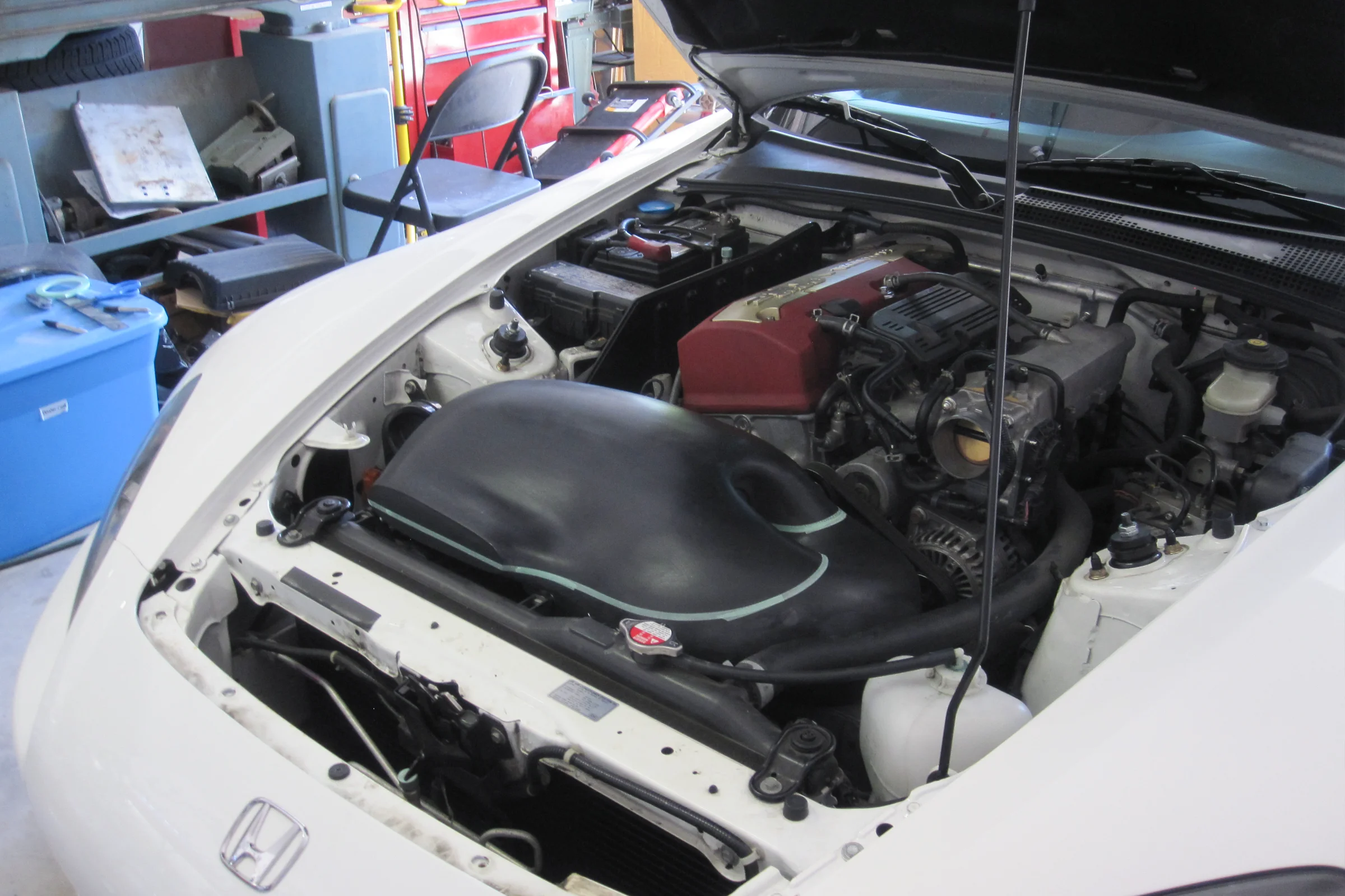
A subsequent full intake enclosure was built to replace the factory airbox entirely: four-part mold, removable access door, larger volume than stock, organically shaped to interface with the snorkel. It was removed after completion. Too complex to replicate and incompatible with biennial California smog compliance. Built it. Learned from it. Pulled it off the car.
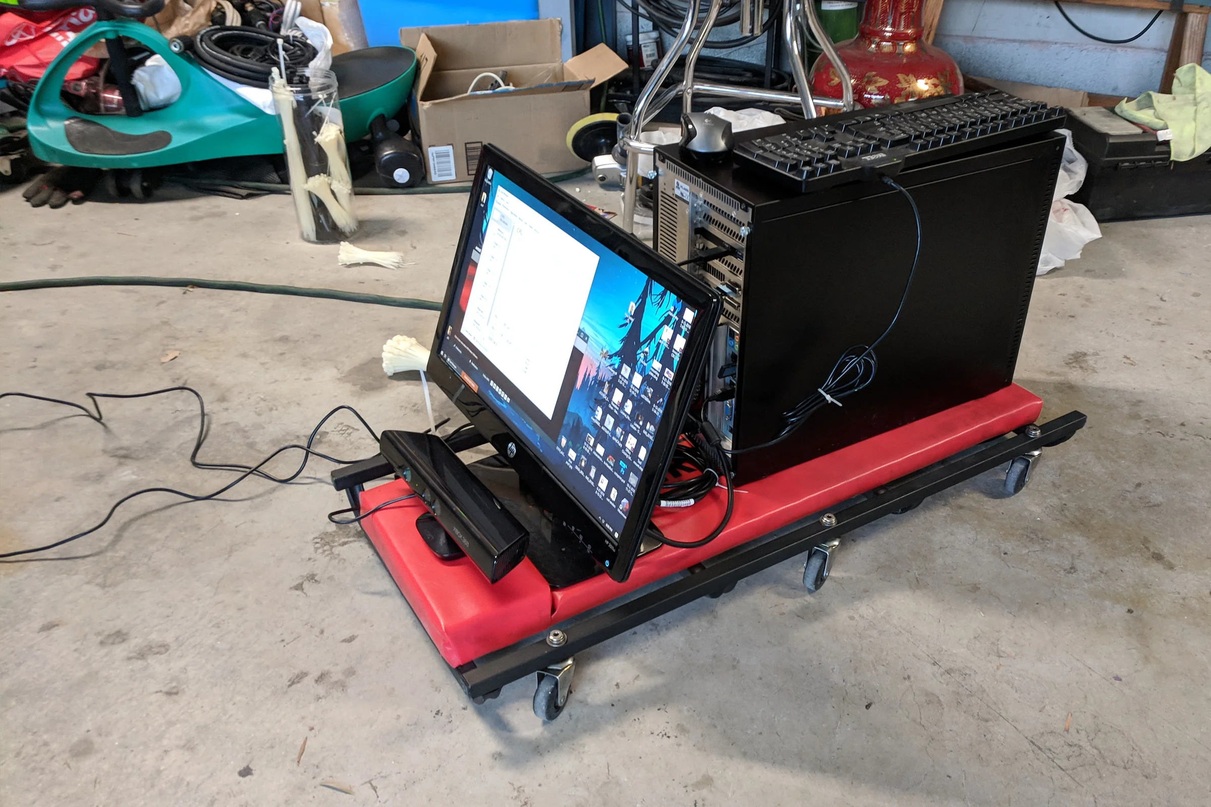
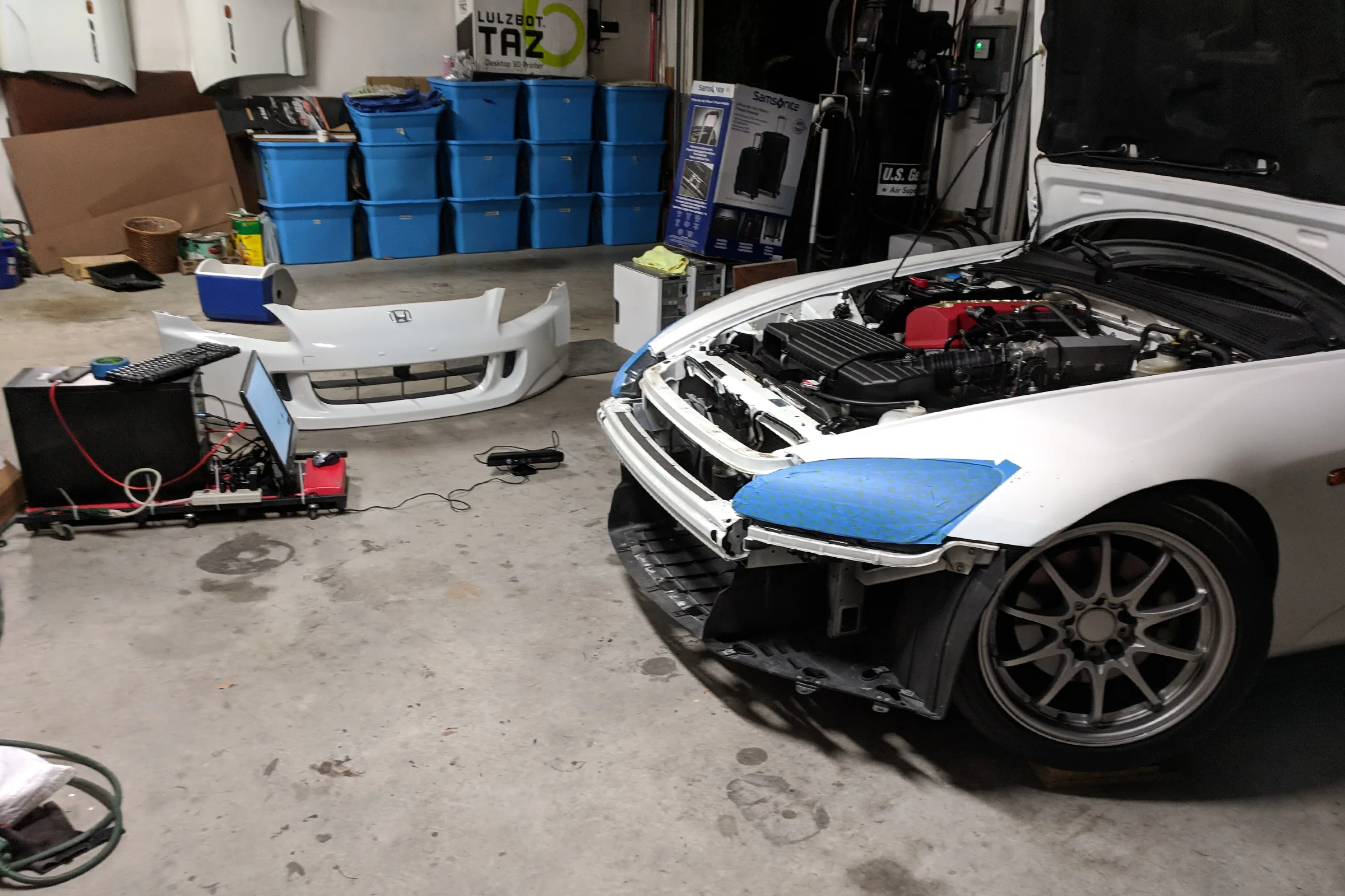
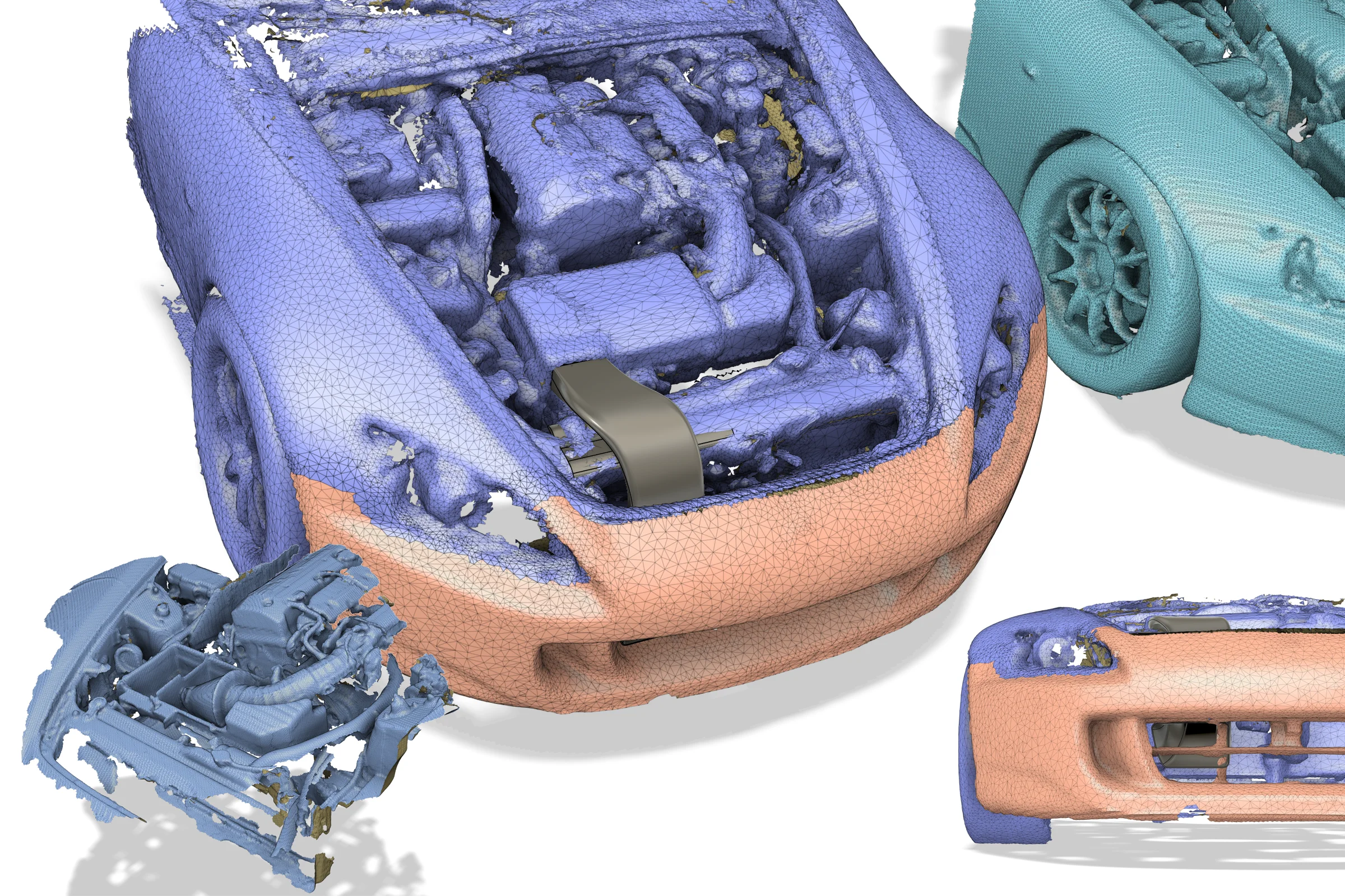
Years later, with early consumer 3D scanning becoming barely accessible through community-hacked Xbox Kinect software, the finished snorkel was scanned into a digital file and the S2000 engine bay was scanned separately. The two were assembled in Fusion 360 for a virtual test fit, which allowed further geometry refinements to increase cross-sectional area at the remaining bottlenecks. A fully optimized version was modeled in CAD but never fabricated. The scan, the model, and the virtual fit are documented on video.
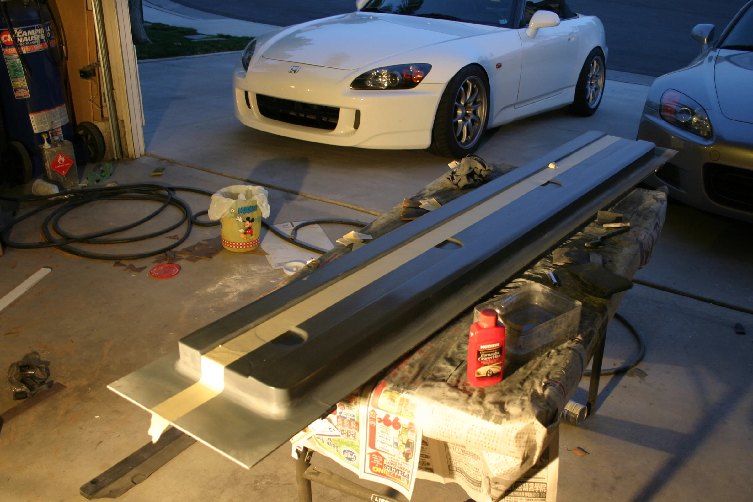
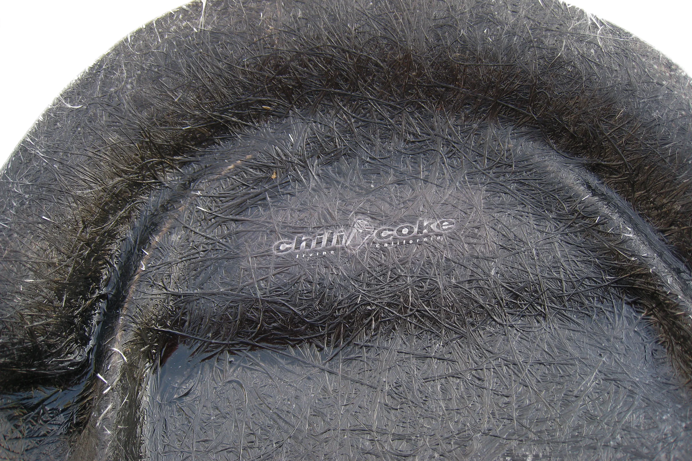
Custom Side Diffusers, Production Jig System
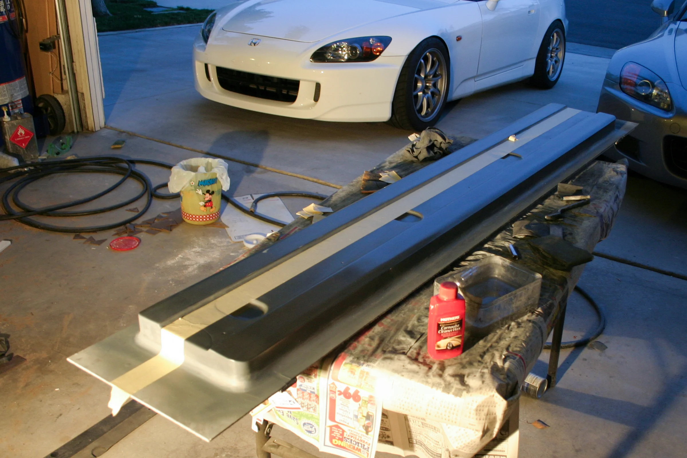
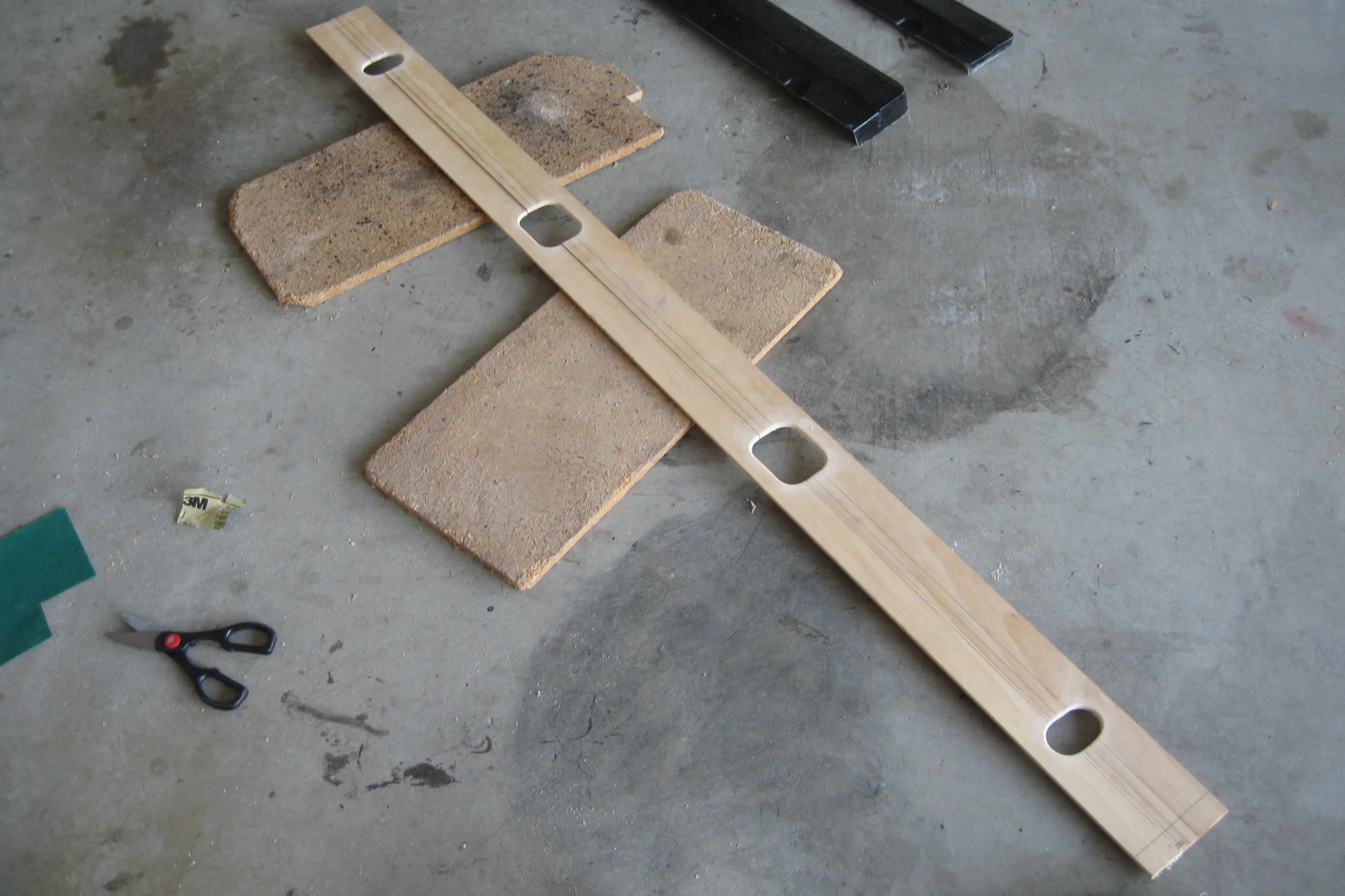
After fitting lower-offset wider tires, the car needed visual balance between the fender width and the side profile. Japanese aftermarket side diffusers for the S2000 ran close to $2,000 for what are, functionally, decorative trim panels. A pair of side diffusers is essentially a flat composite slab with a consistent cross-section, which meant the shape already existed at Home Depot for $3 a yard in baseboard molding.
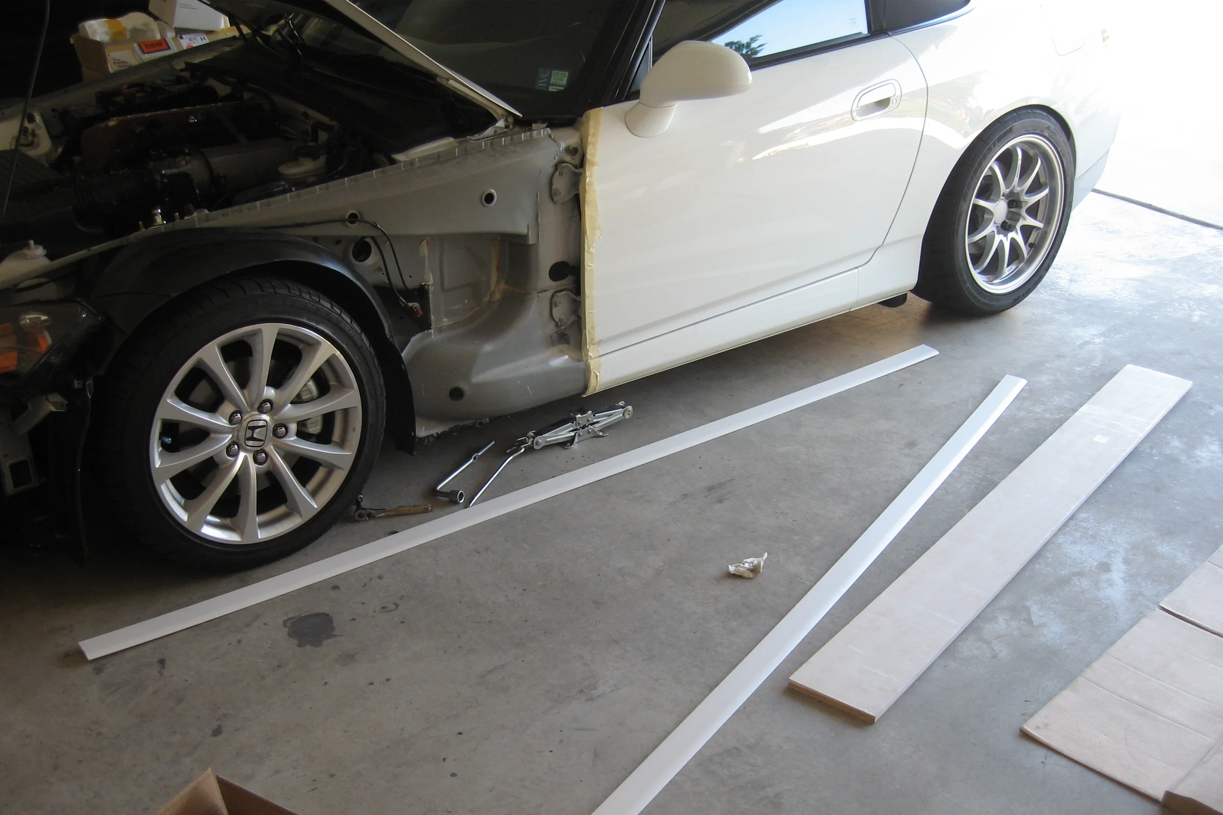
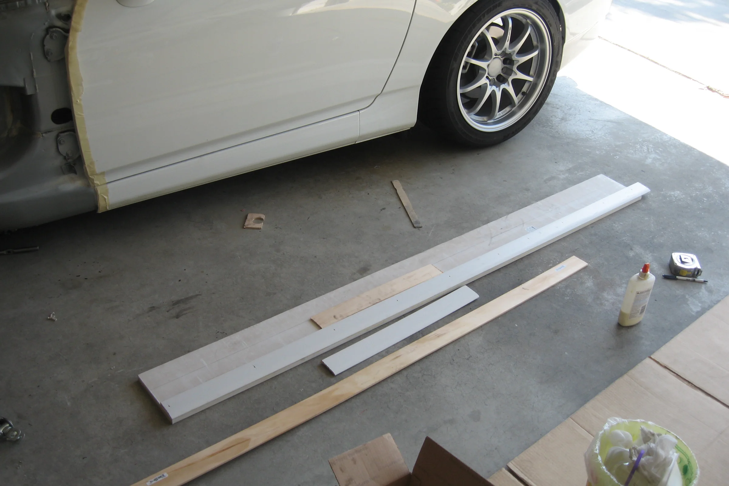
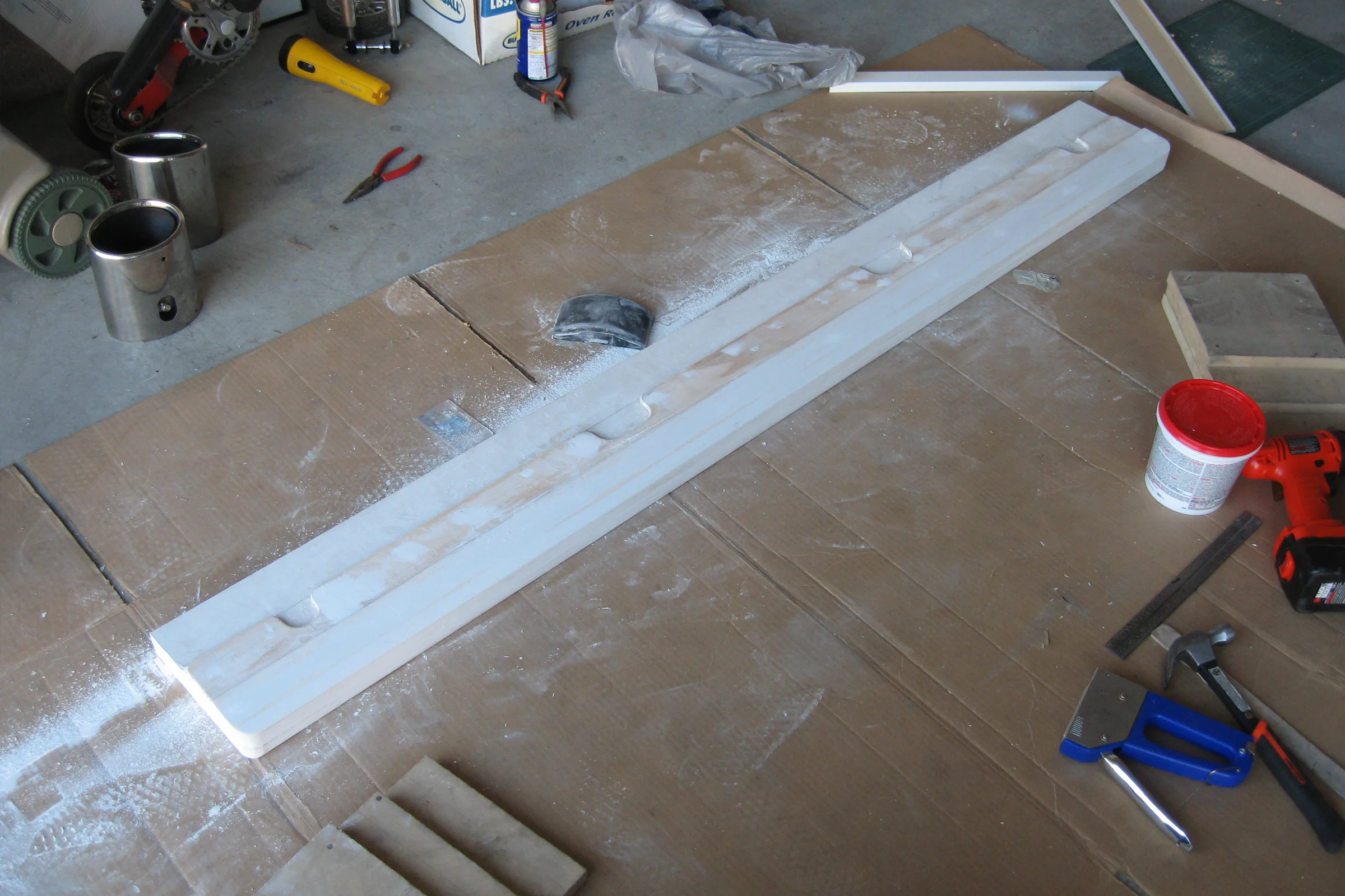
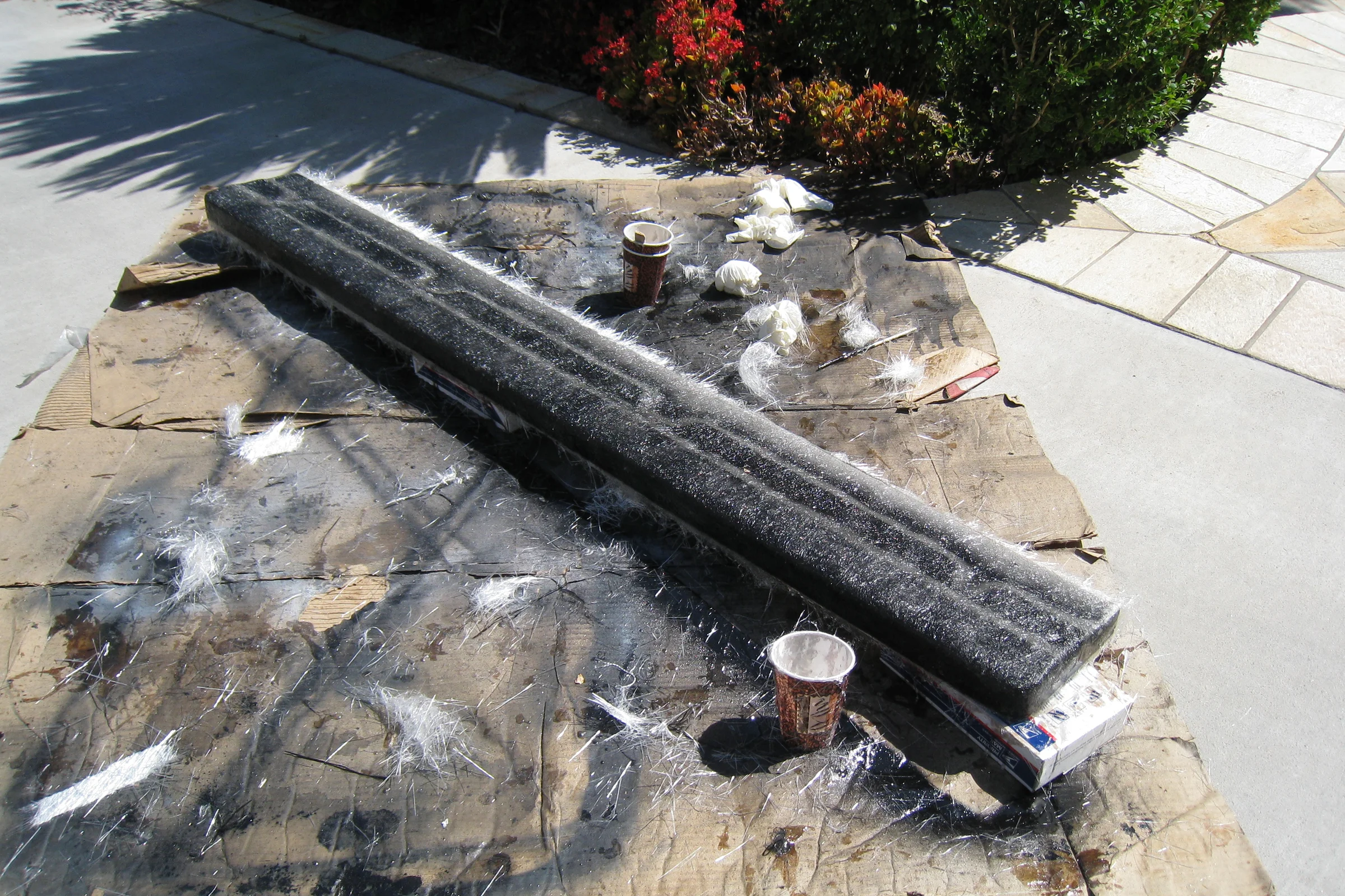
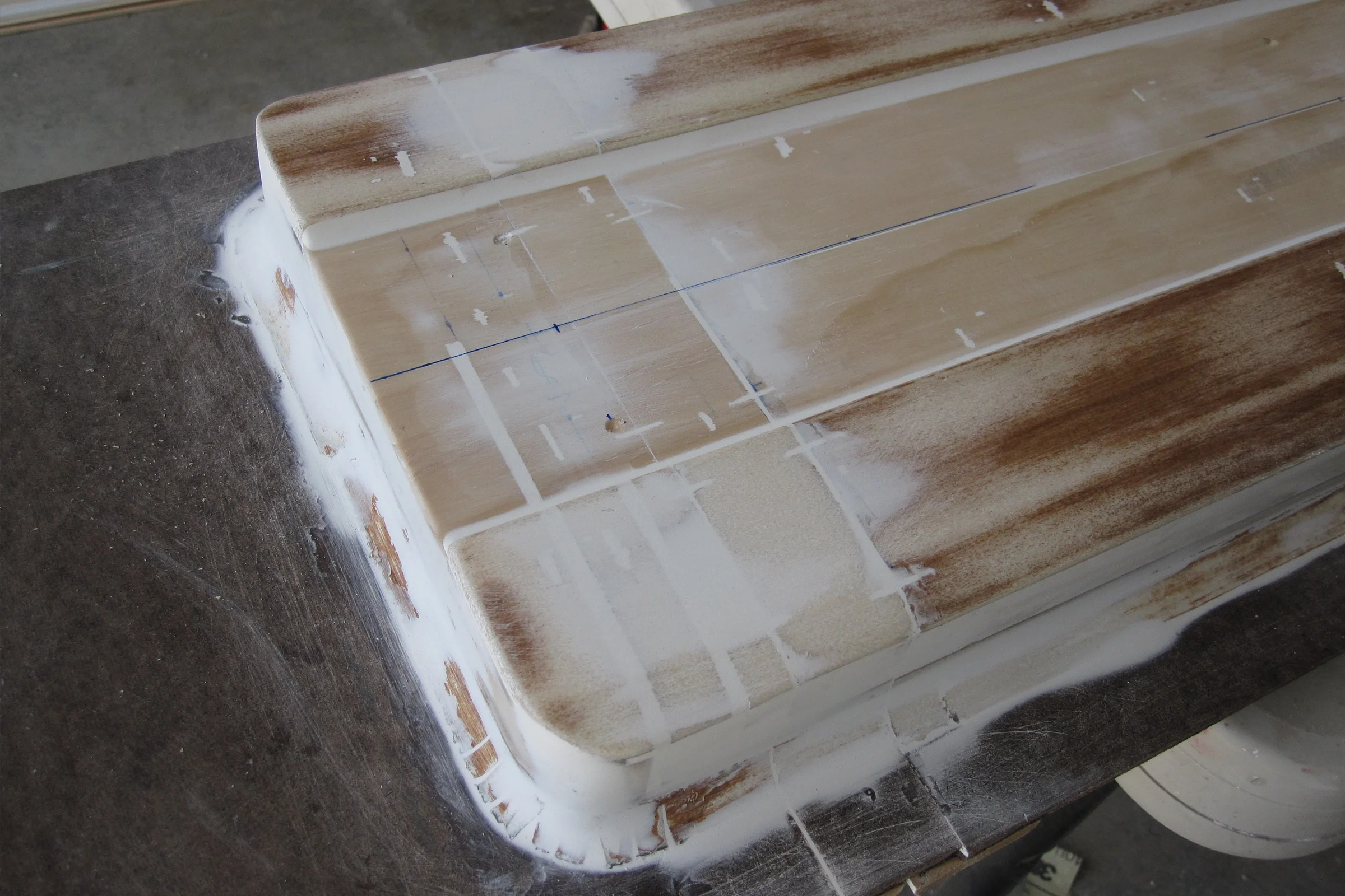
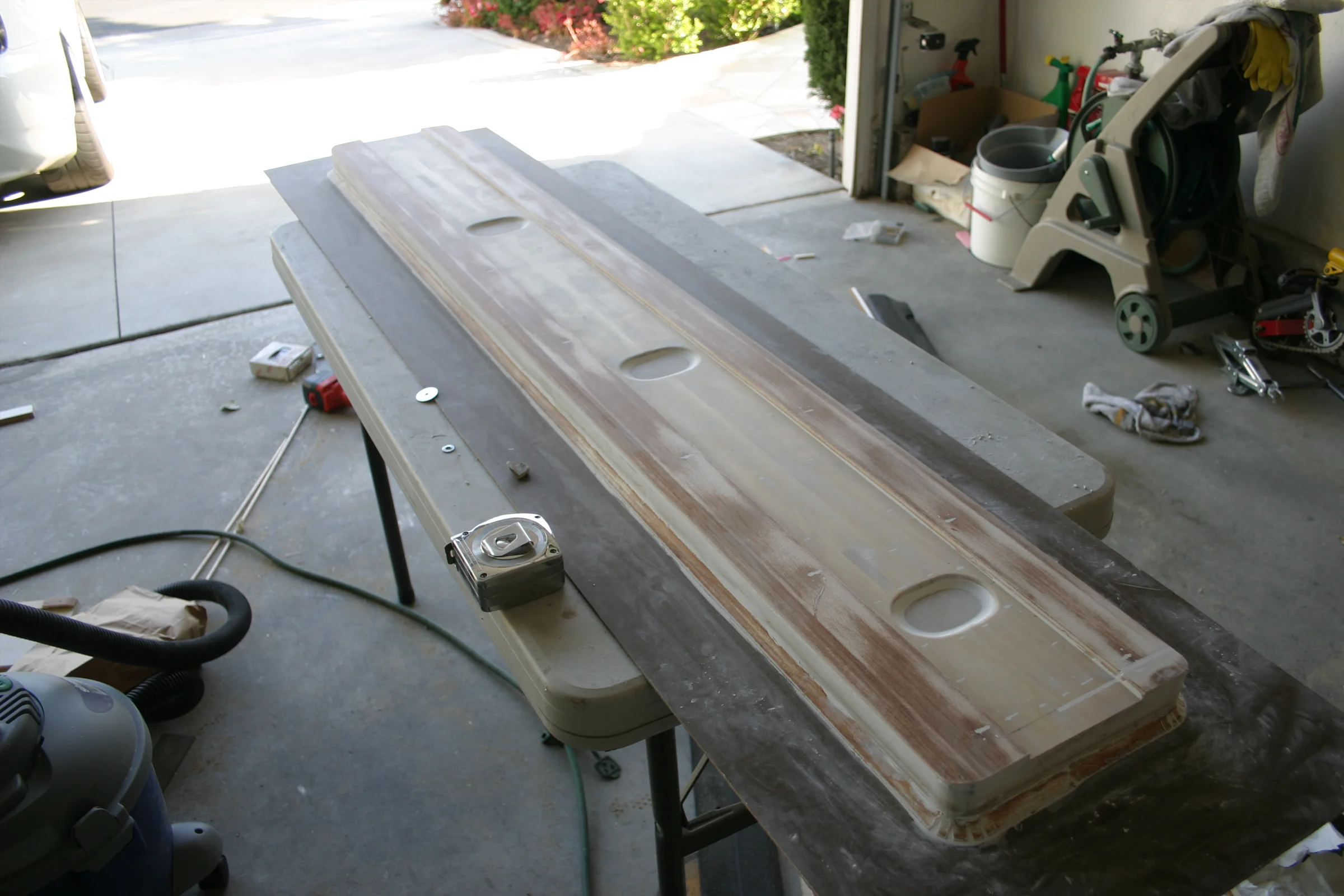
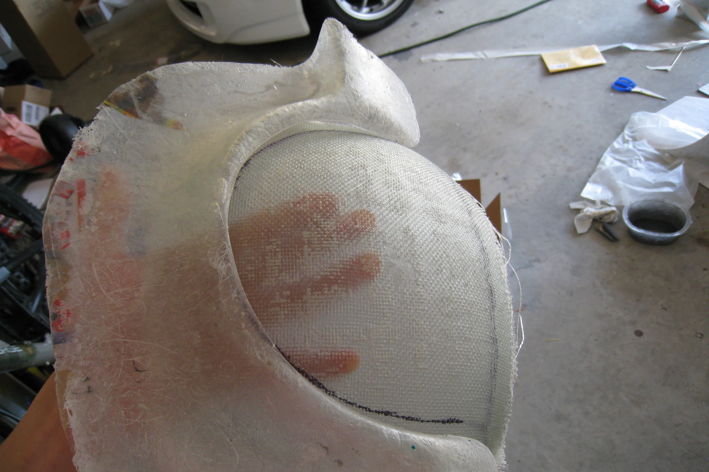
The look was already validated on a scrappy wood mockup. The first mold was a process test: pull a proper fiberglass part, mount it on the car, and road-test real fitment before committing to a refined design. The plug was built from wood, cut, shaped, glued, and sanded into the target profile, then sprayed in high-fill primer and block-sanded smooth. A crude mold was pulled, one set cut and mounted.
Road testing exposed real problems with the approach. A truly side-agnostic shape is a fitment compromise on both sides of the car. Producing a pair required pulling the same mold twice, which was slow. And manually trimming a long flat piece to consistent length was labor-intensive. The design was scrapped entirely.
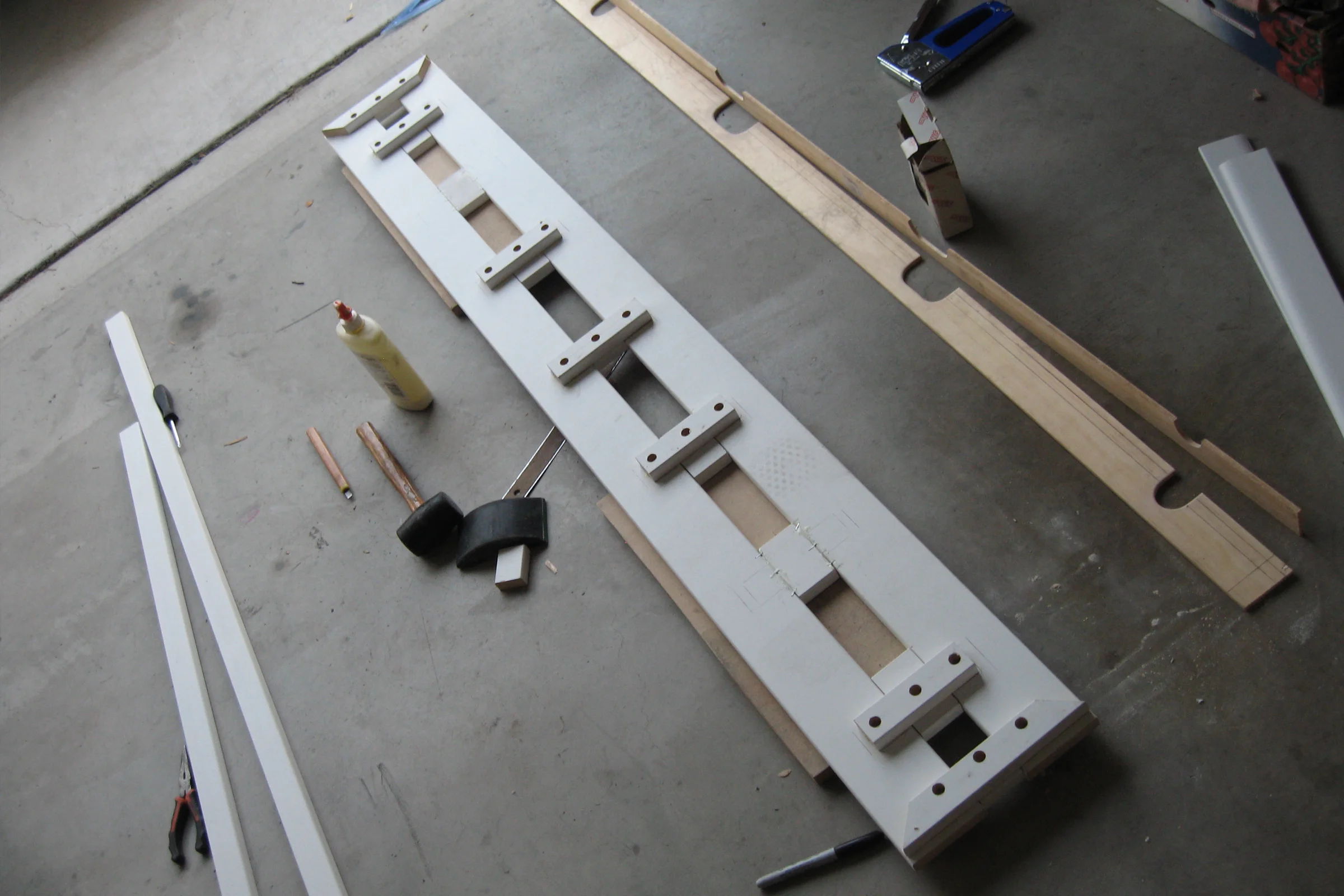
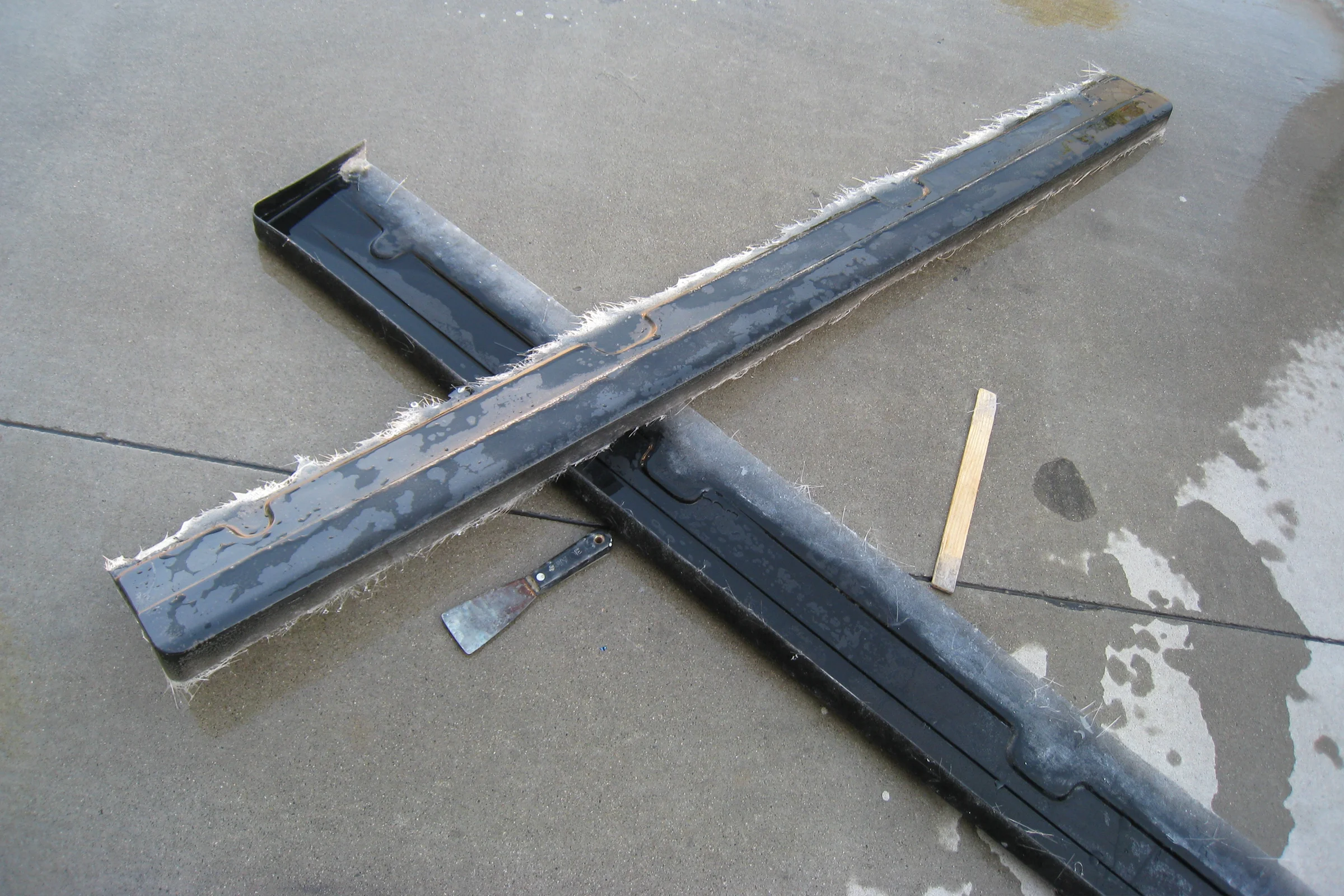
The second plug was also built from wood, with revised geometry addressing the fitment compromises found on the first version. The key redesign decision was to build both sides as a single unified piece, both diffusers mirrored and joined, rather than two separate halves. One plug, one mold, one pull produces both sides simultaneously.
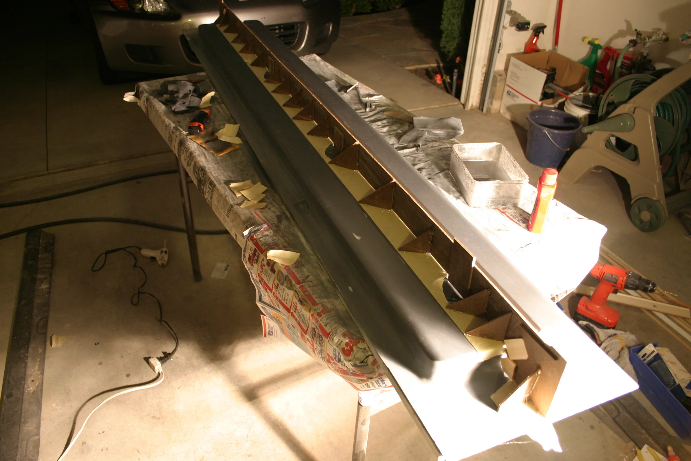
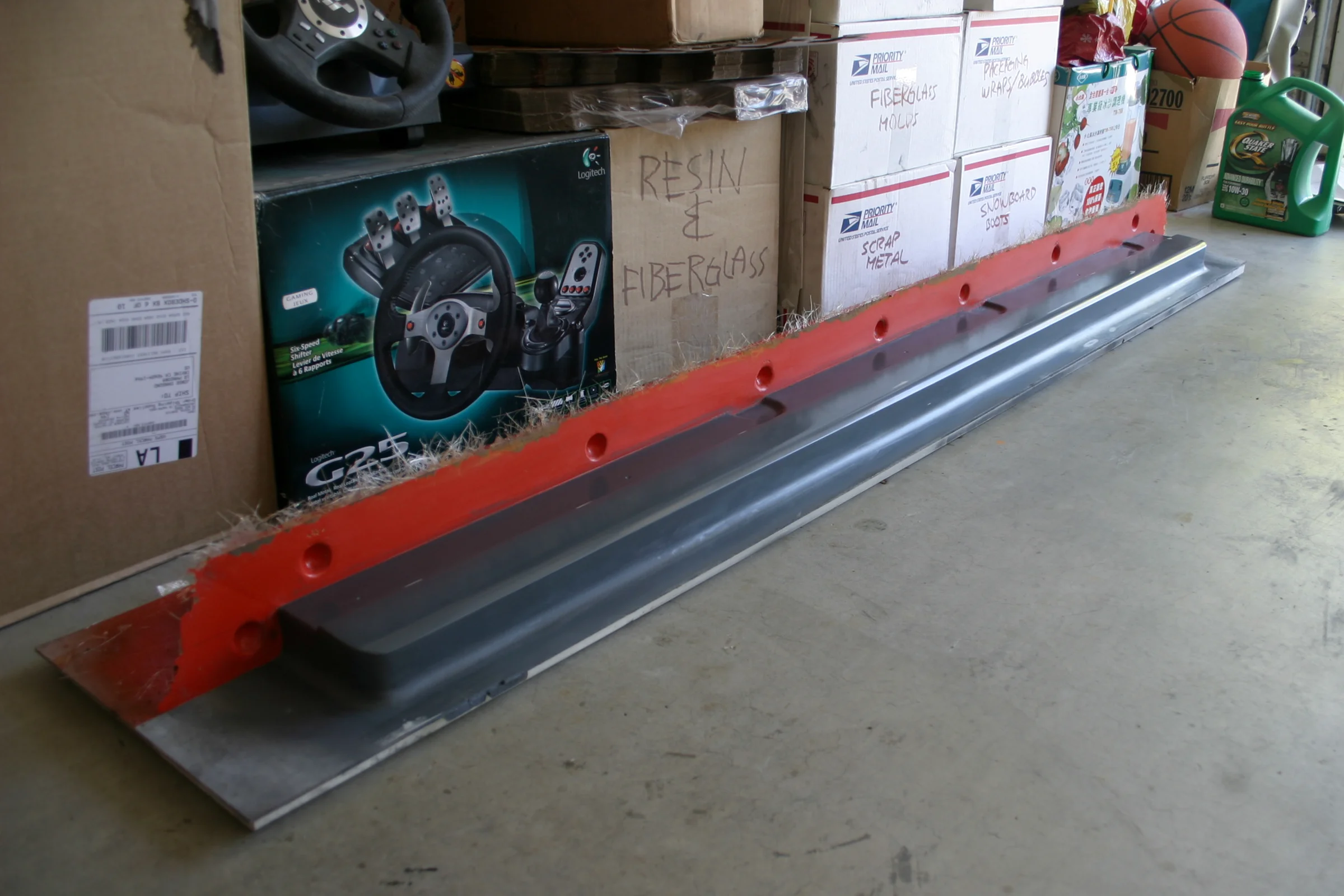
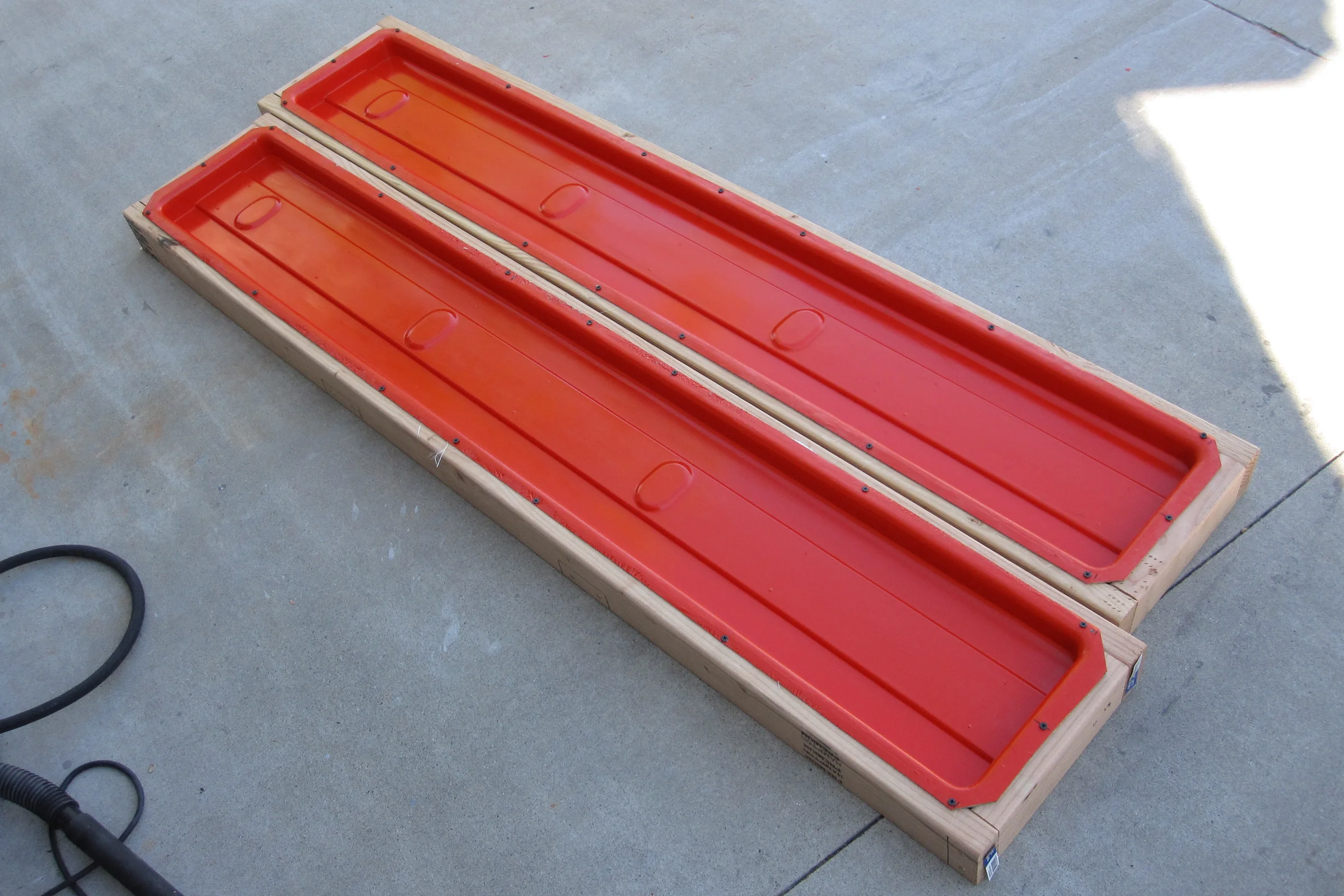
The unified double-width shape created a demolding problem. The part is long and thin with flat parallel sides, the mold profile resembling a very long, narrow Tupperware container. Even with flat walls, a mold that shape can trap the part if the mold deforms over time. The mold was designed as two pieces, flange-jointed at the center, so the halves bolt together for layup and separate for demolding, eliminating the trap entirely. Wooden cradles were built to hold the assembled mold upright during fabrication, keeping the parting flange clear of the table surface.
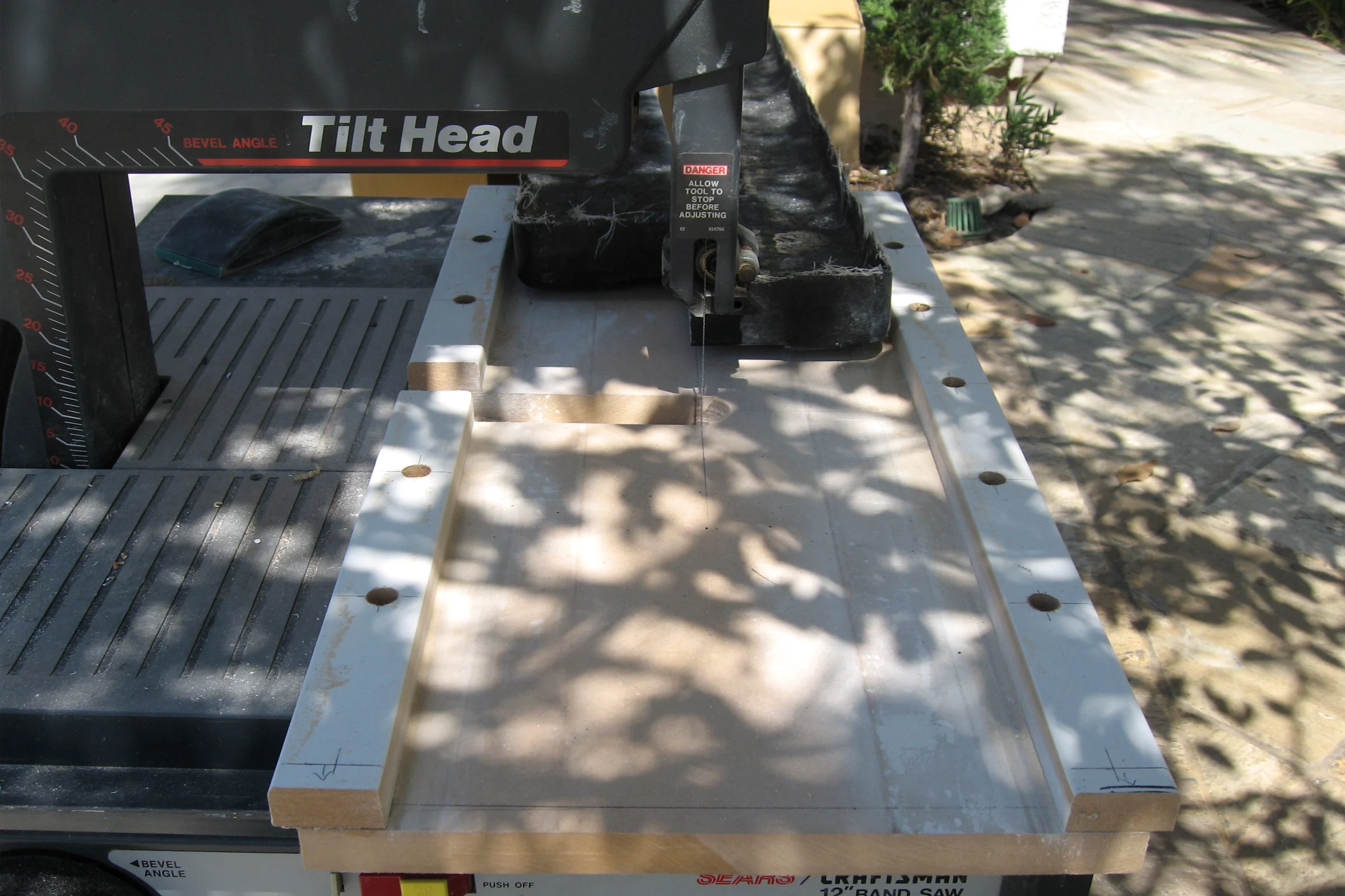
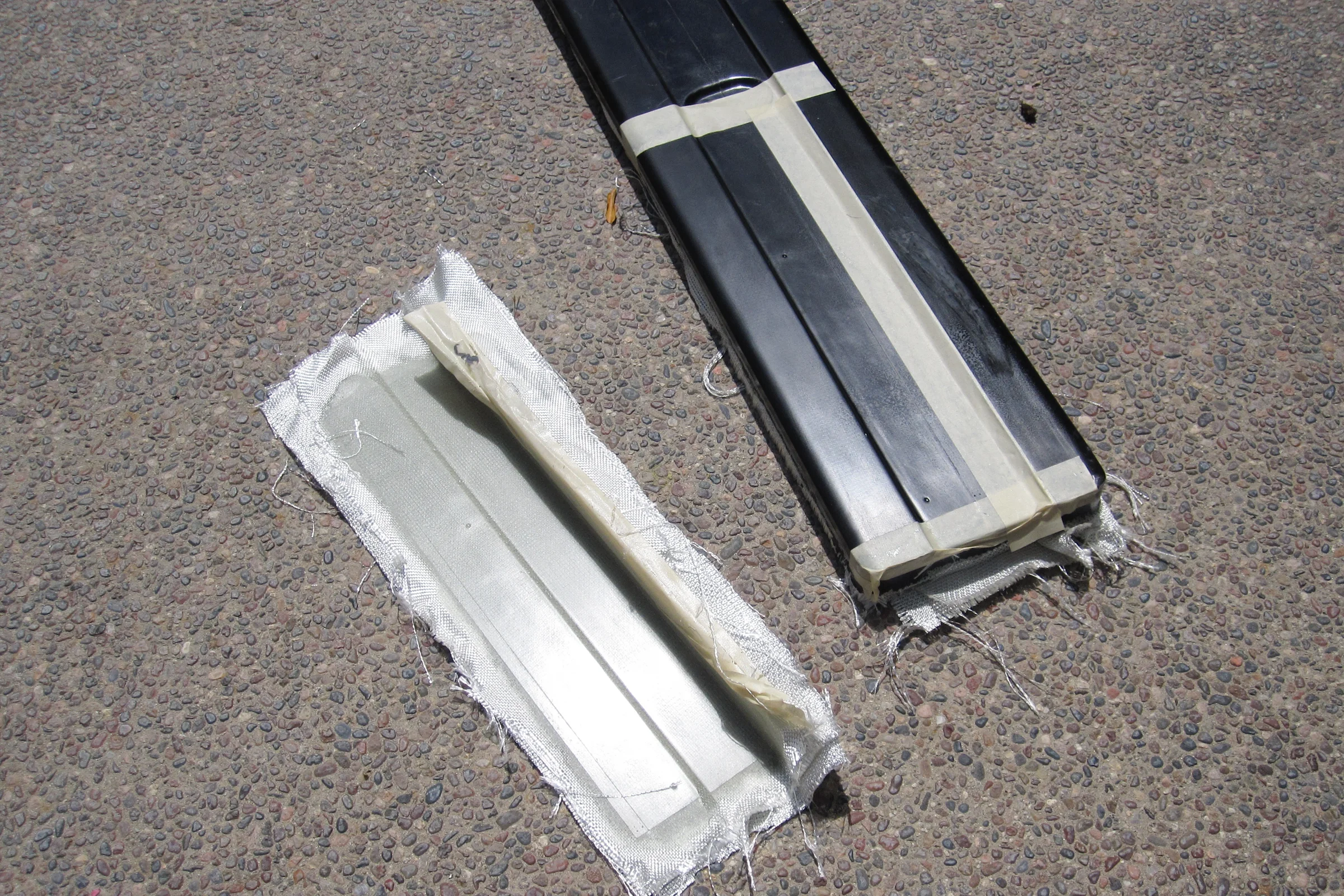
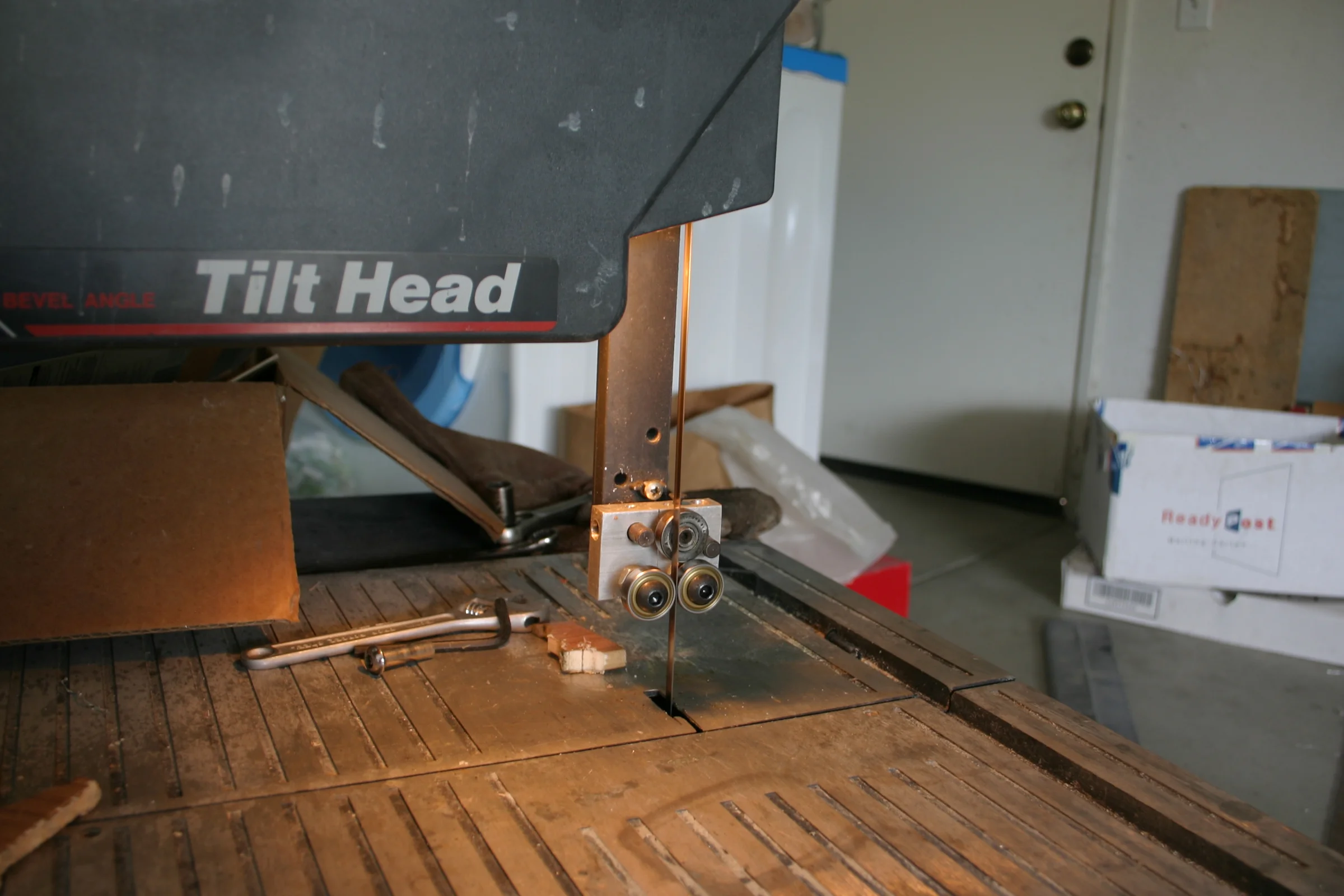
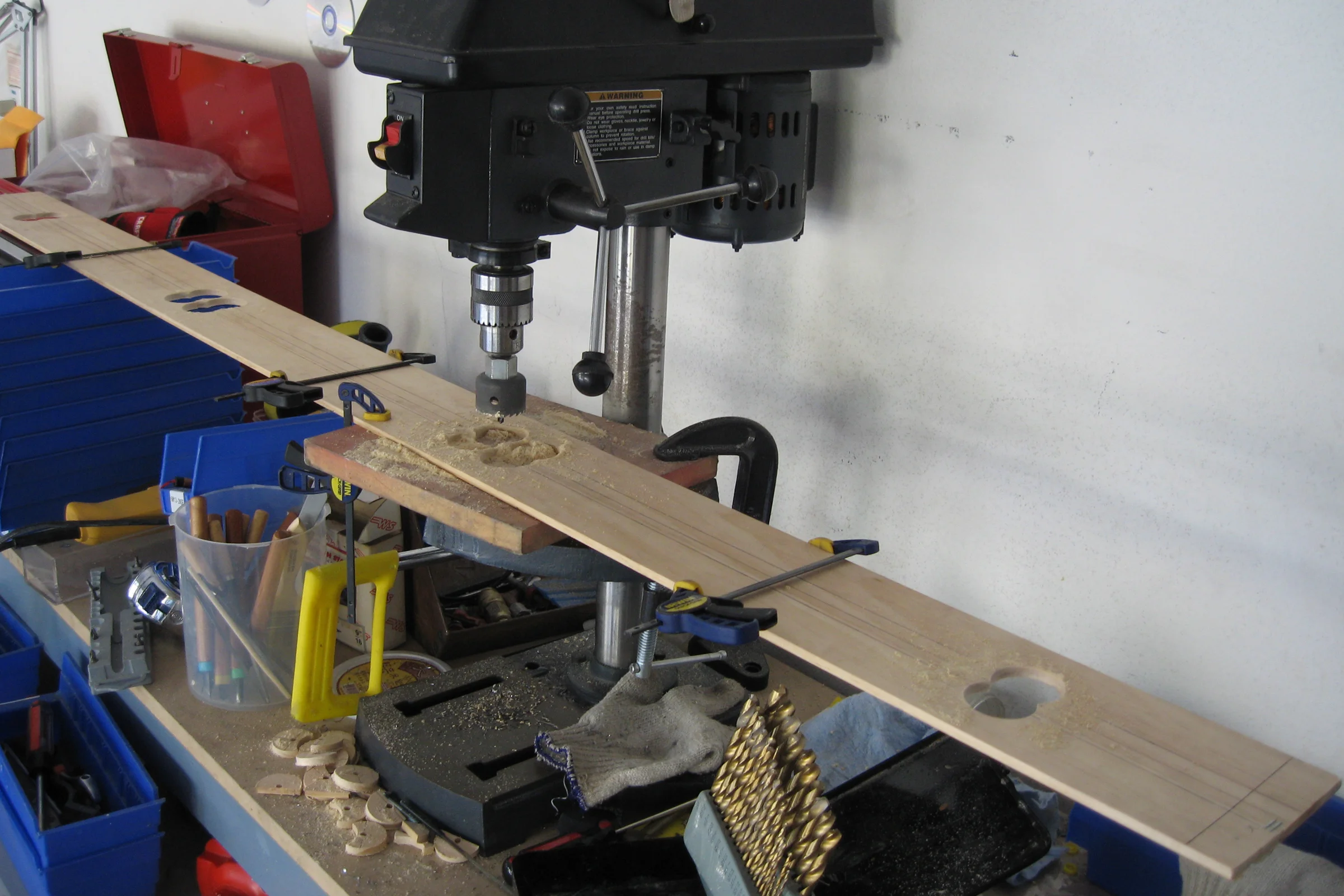
Freehand cutting was not an option on either cut. The solution was two purpose-built jigs. The first, built from wood as the fastest material to work with, clips onto the bandsaw and registers the pulled part at exact center for the lengthwise center split, dividing every pull into two identical halves in under a minute with zero measuring. The second jig handles the edge trim cut, which runs the full length of each piece approximately 5mm from the most visible long edge, any deviation reads immediately on the installed part. A 12-inch section of a first-pull part was used as a mold to cast a short fiberglass form, trimmed to the exact profile and mounted vertically on the jig base. Each piece slides along this guide in the correct orientation, referenced to the same profile dimension on every cut. The bandsaw itself was also improved: a self fabricated ball bearing blade guide replaced the factory guide for better blade tracking. The whole system had to work together to produce a consistent result.
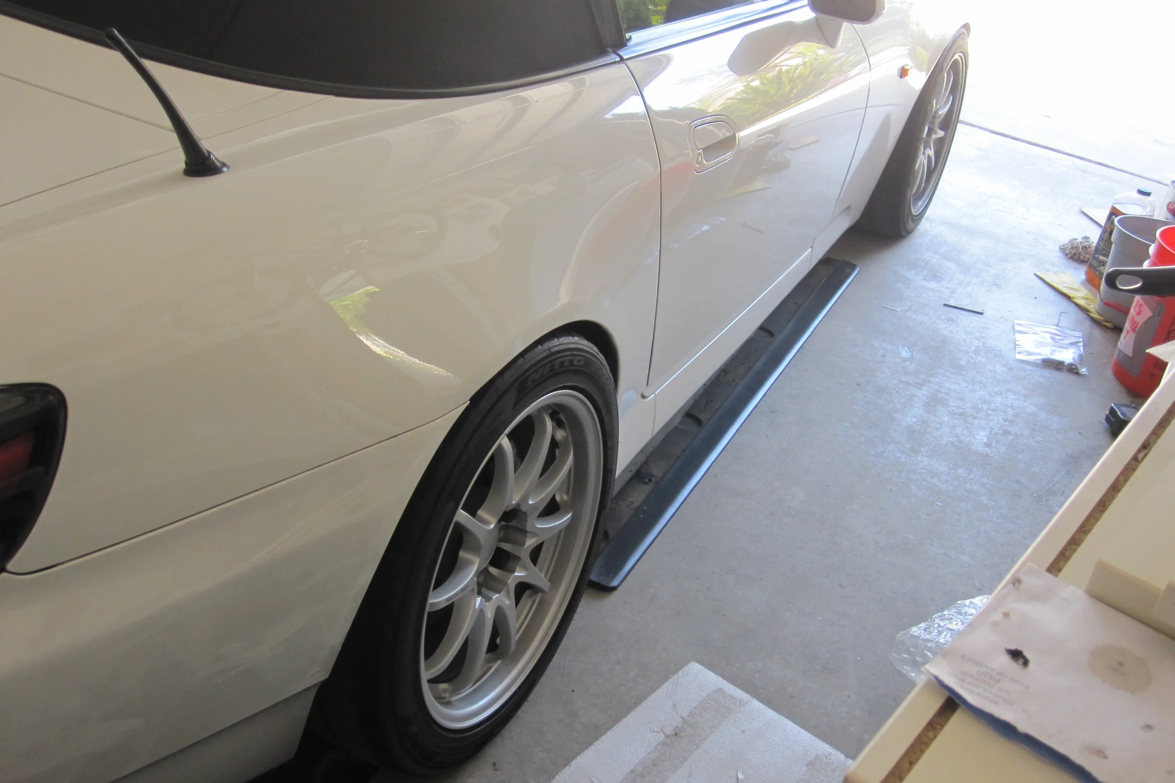
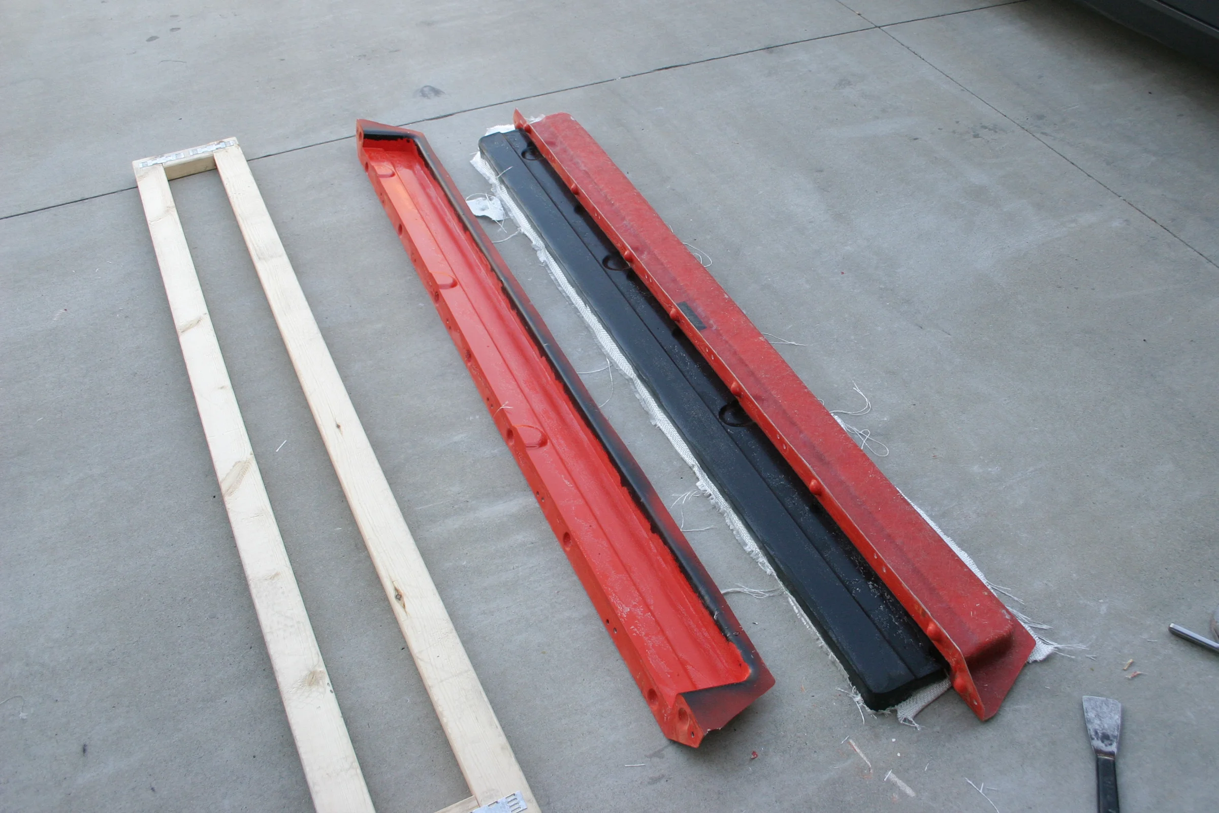
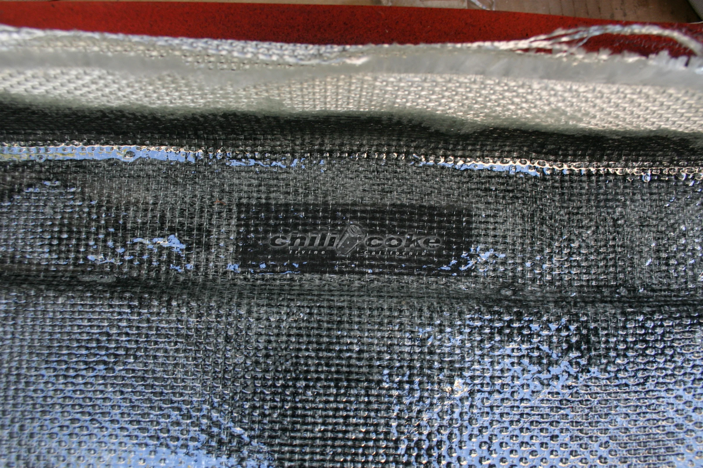
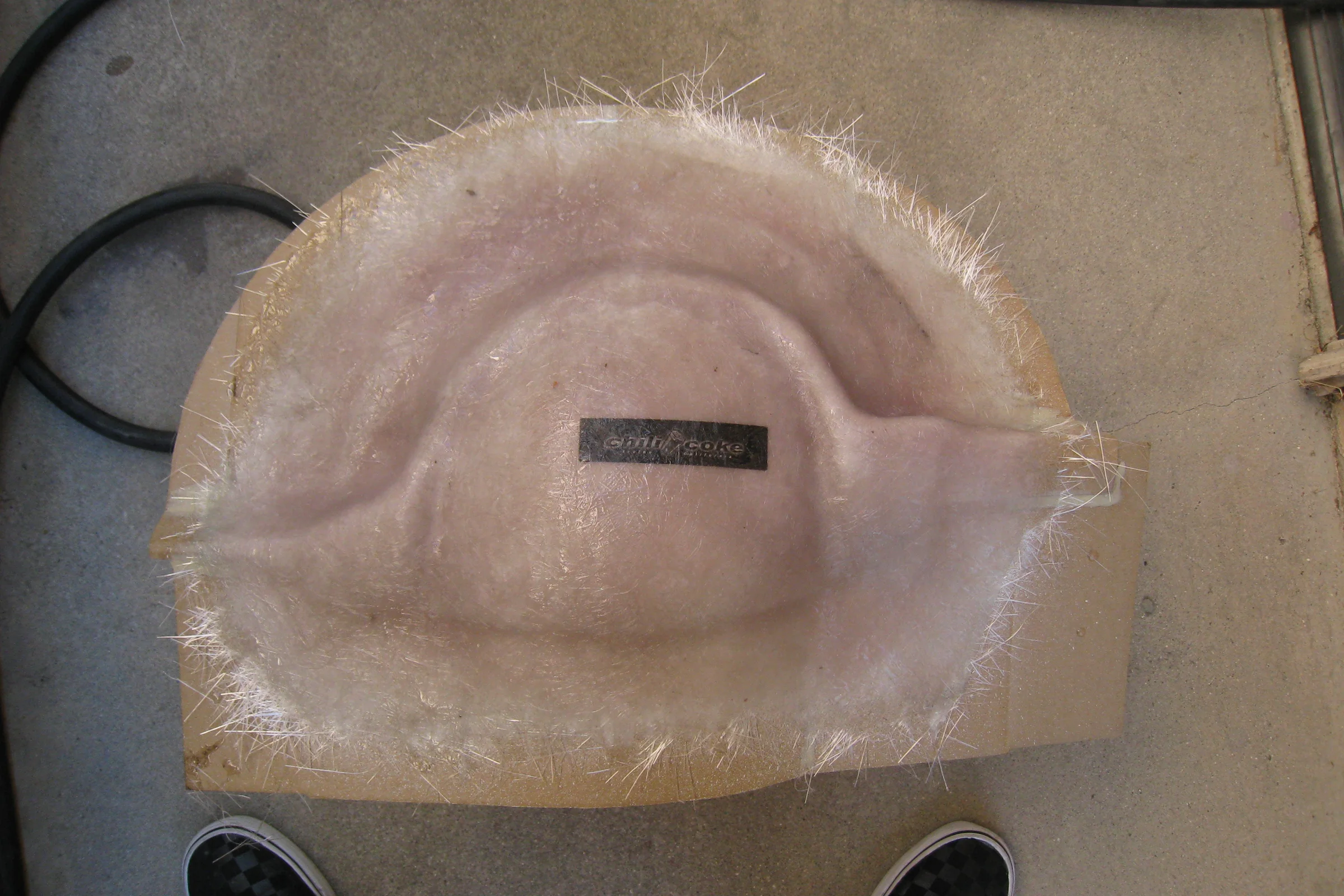
The two-piece split mold also made it possible to test-pull complete double-width parts without splitting them, and it turned out splitting to demold wasn't actually necessary at all. The part releases cleanly from the assembled mold in one pull, eliminating the unbolting, the joint line flash cleanup, and the time cost of both. After confirming sustained demand, a final single-piece plug was made by pulling one fresh part from the existing mold, building new flanges onto it before any trimming, and using it as the basis for the final molds. Multiple molds were pulled from that same plug. Each finished mold is permanently fixtured to a wood frame to prevent the long center walls from flexing inward under part shrinkage pressure. The plug itself was later trimmed into a finished set and sold. Multiple molds and cradles were built in parallel, allowing multiple sets to be fabricated simultaneously. Over 100 sets were sold to other S2000 owners, each with the Chilicoke logo embedded in the layup. The jigs weren't planned for commercial production. The commercial production happened because the jigs made it effortless.
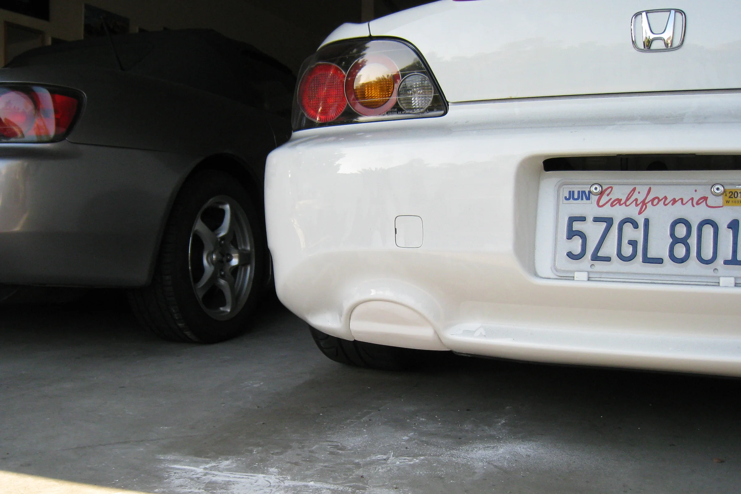
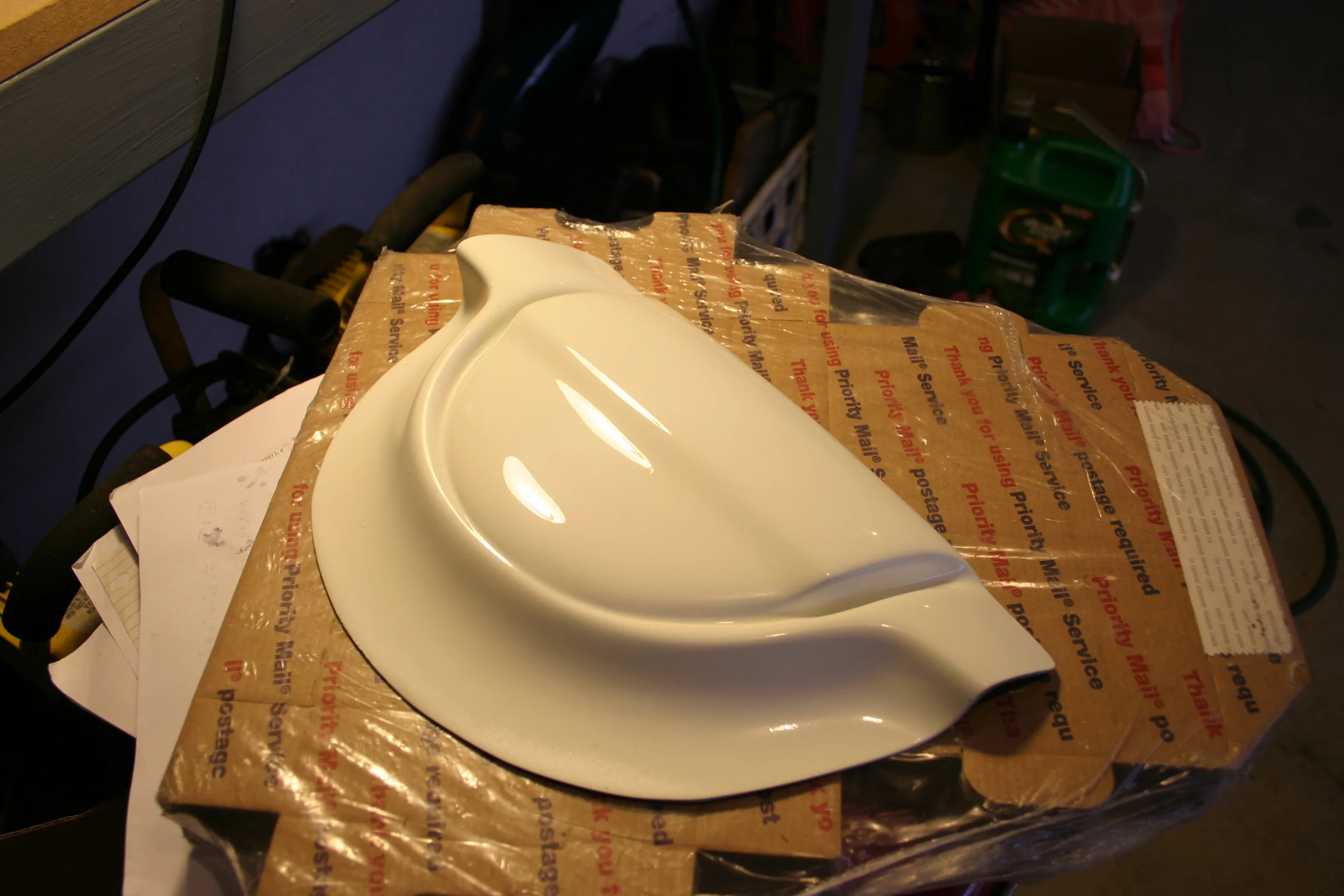
Single Exhaust Cover, Community Iteration Loop
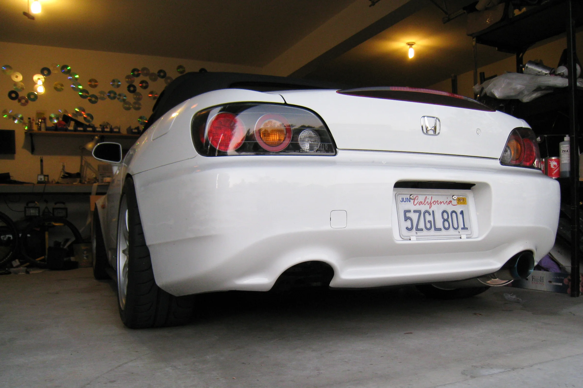
The AP2 S2000's rear bumper integrates the dual exhaust tips into the bumper design. Converting to a single exhaust, a common weight-saving modification, left a large open hole on one side. No aftermarket cover existed for the AP2 bumper. The first design approach was logical: find an object with the right curvature, lay fiberglass over it, trim and bond into a bezel. A pool ball from Walmart matched the exhaust opening radius closely enough to work. The result fit correctly and covered the hole completely.
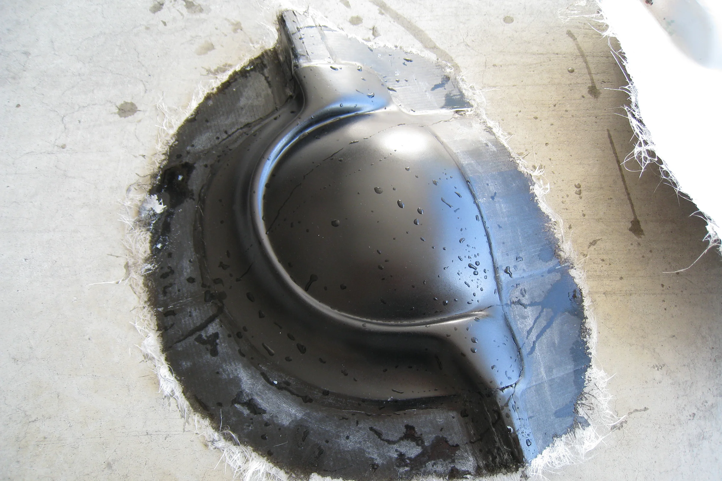
The forum response was immediate and unanimous: it looked like the car was laying an egg. Which was, objectively, accurate. The exhaust cutout itself is rounded, so the geometry wasn't wrong at the opening, but the pool ball radius domed outward in a way that clashed with the S2000's otherwise sharp, straight rear bumper lines the moment you stepped back from the hole. Rather than argue, the post was updated with the original photo, egg crack drawn over it. Then the design was scrapped entirely.
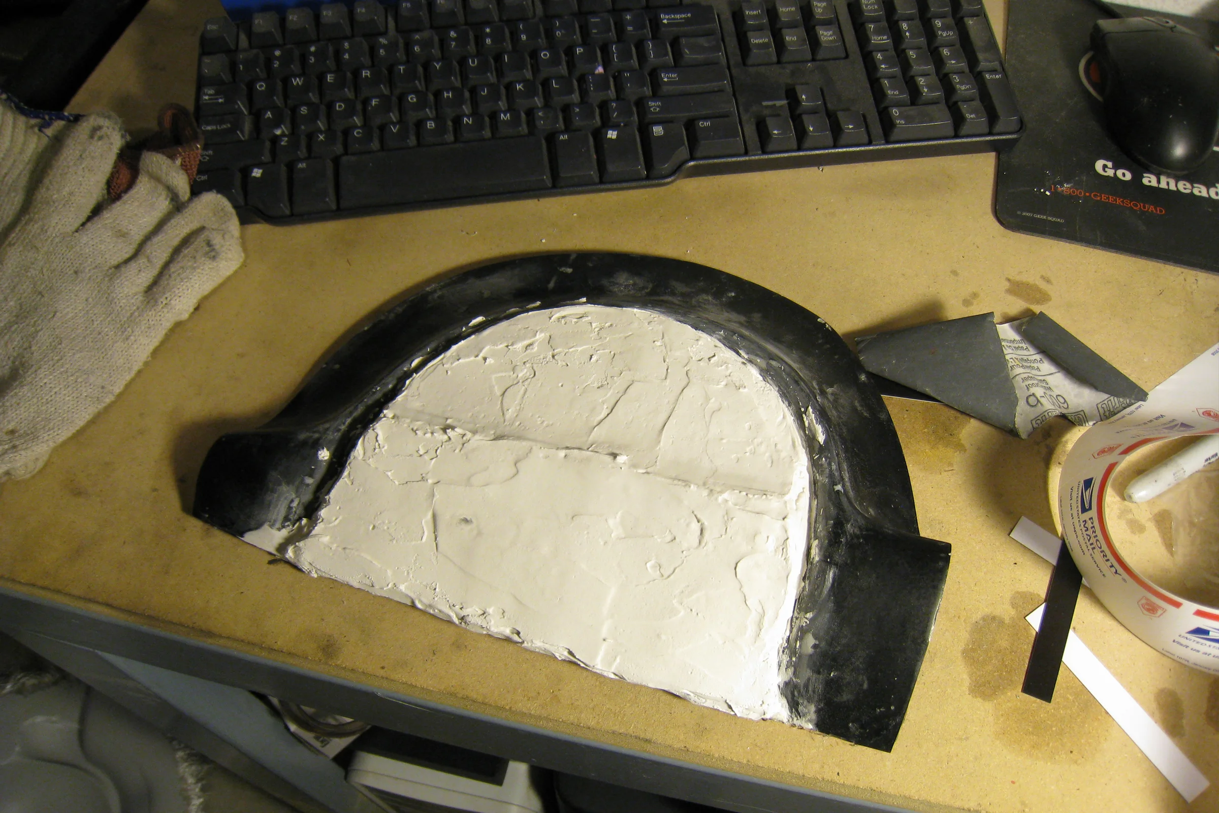
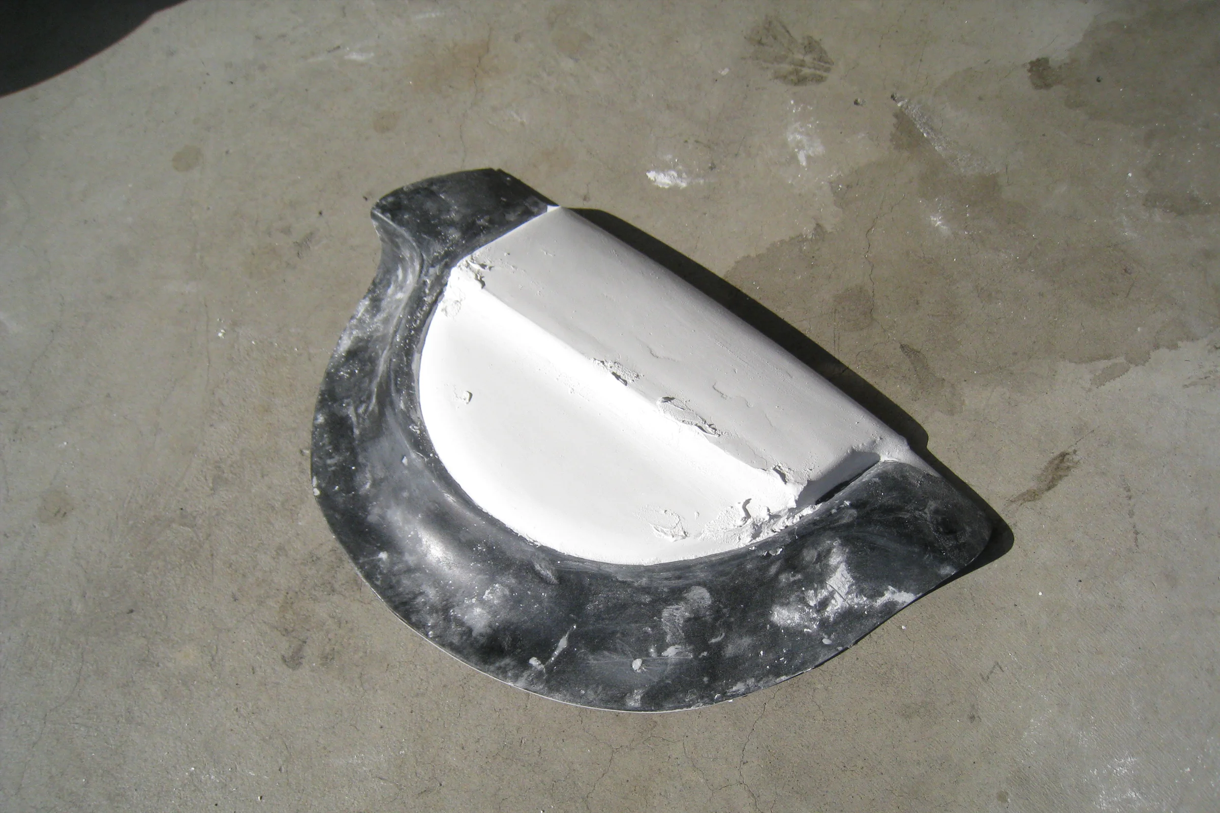
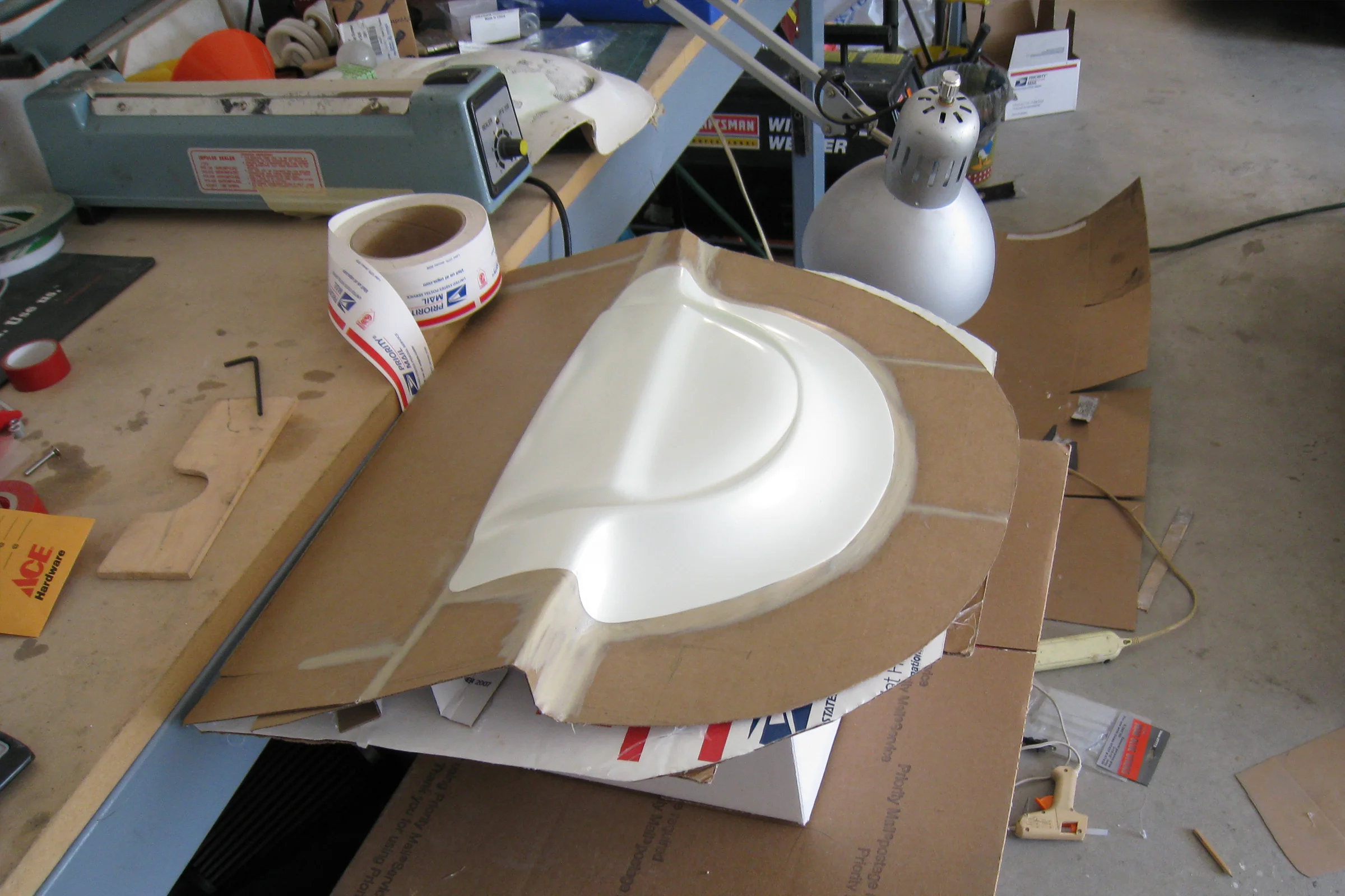
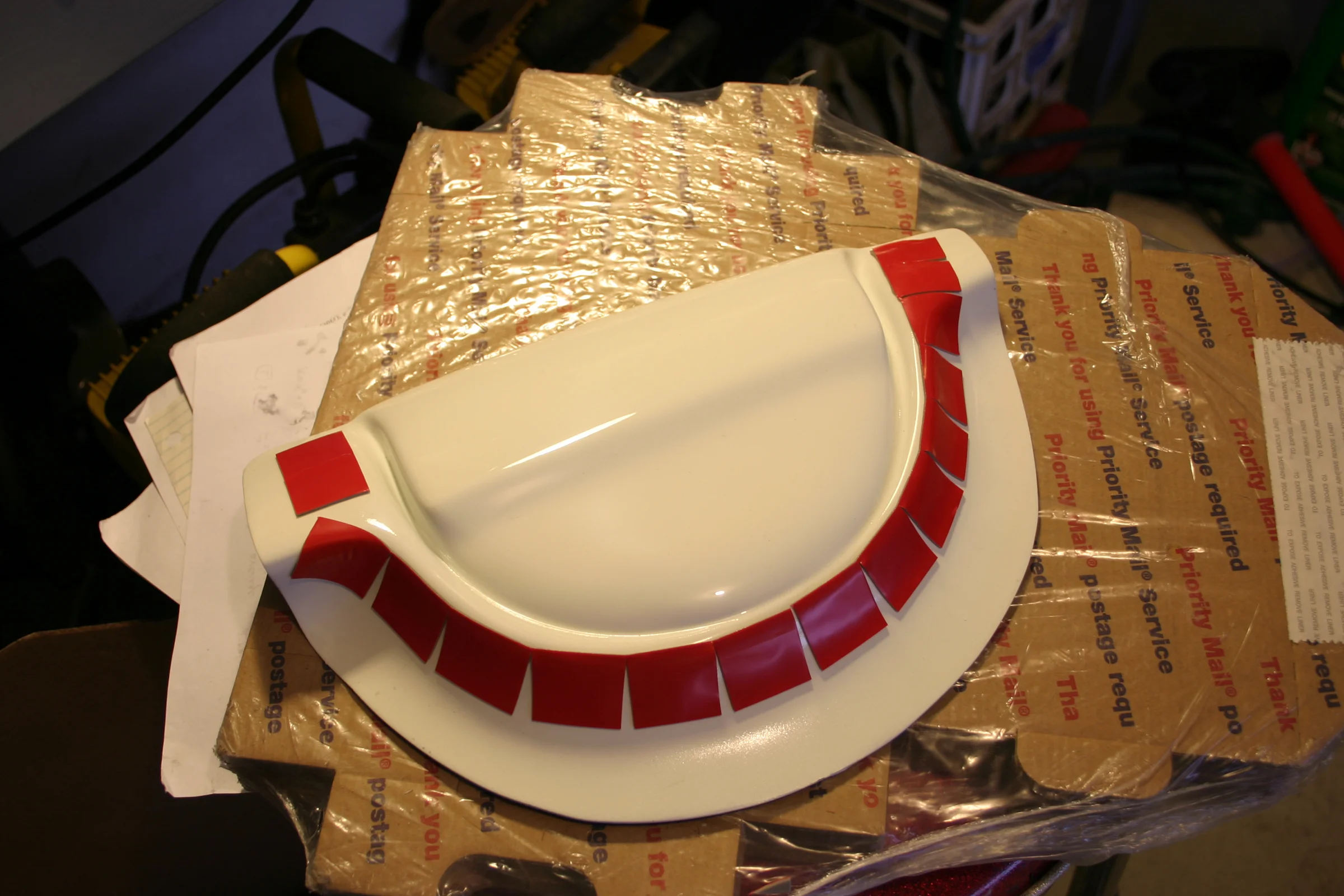
The second approach started with plaster instead of geometry. Sculpted directly against the bumper surface, working to the car's actual line language rather than to the nearest convenient geometry. When something read correctly, it was sprayed in rattle-can primer at rough color match and photographed back on the car. The photo went back to the forum before the mold was started. The community response reversed completely, approval on the shape, and unsolicited interest in buying one. Only then was the mold built. Over 100 covers were sold. The lesson was about sequencing: get external validation before committing to tooling, not after.
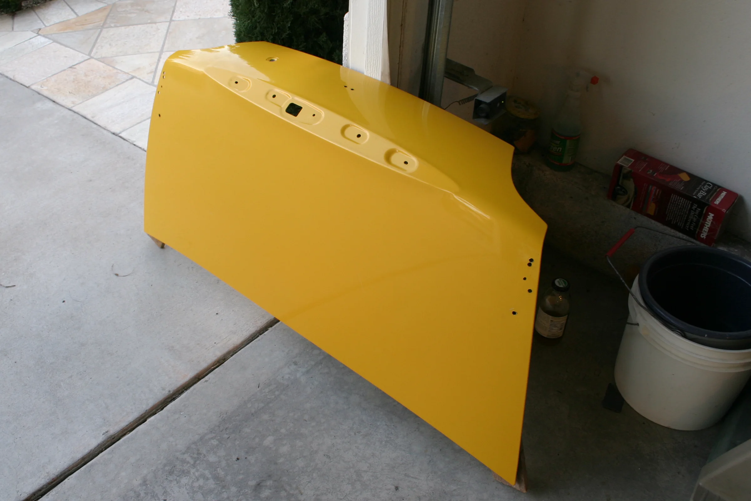
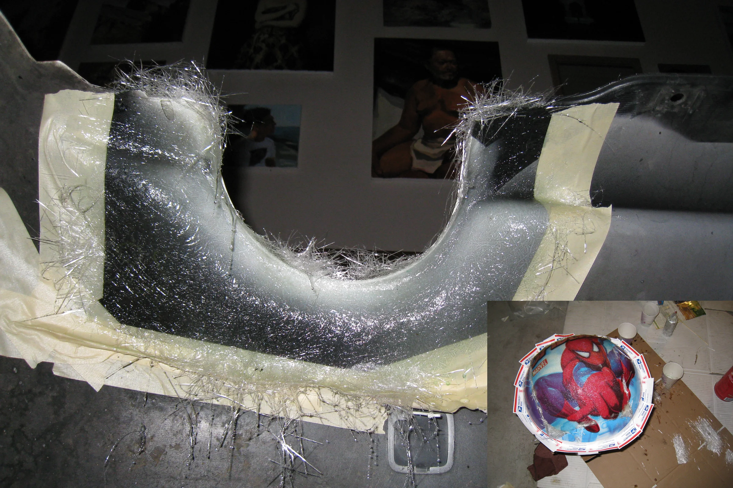
Amuse Bumper, Repair, Fit, Mold, and Paint
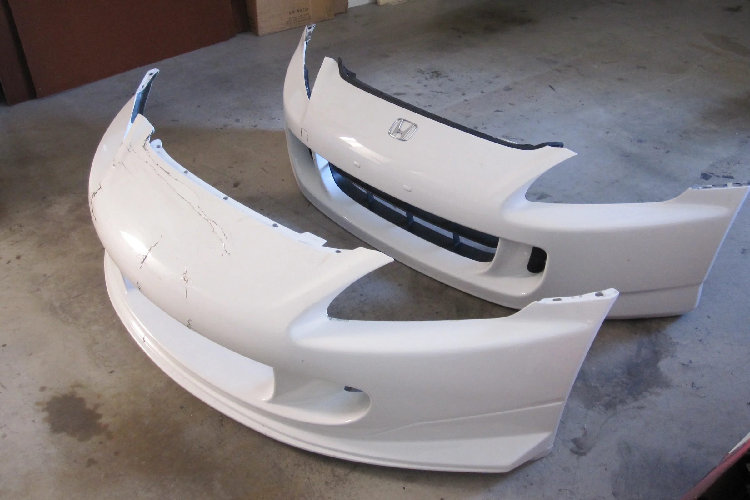
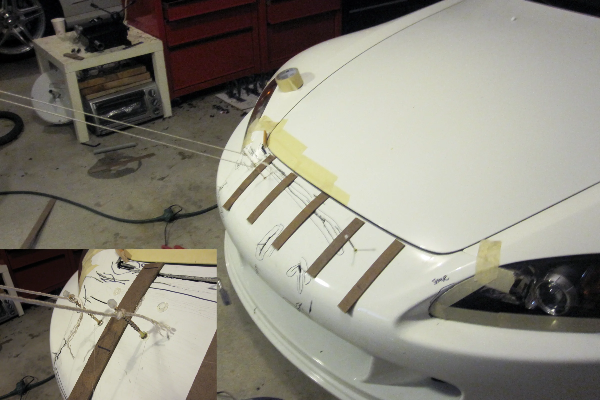
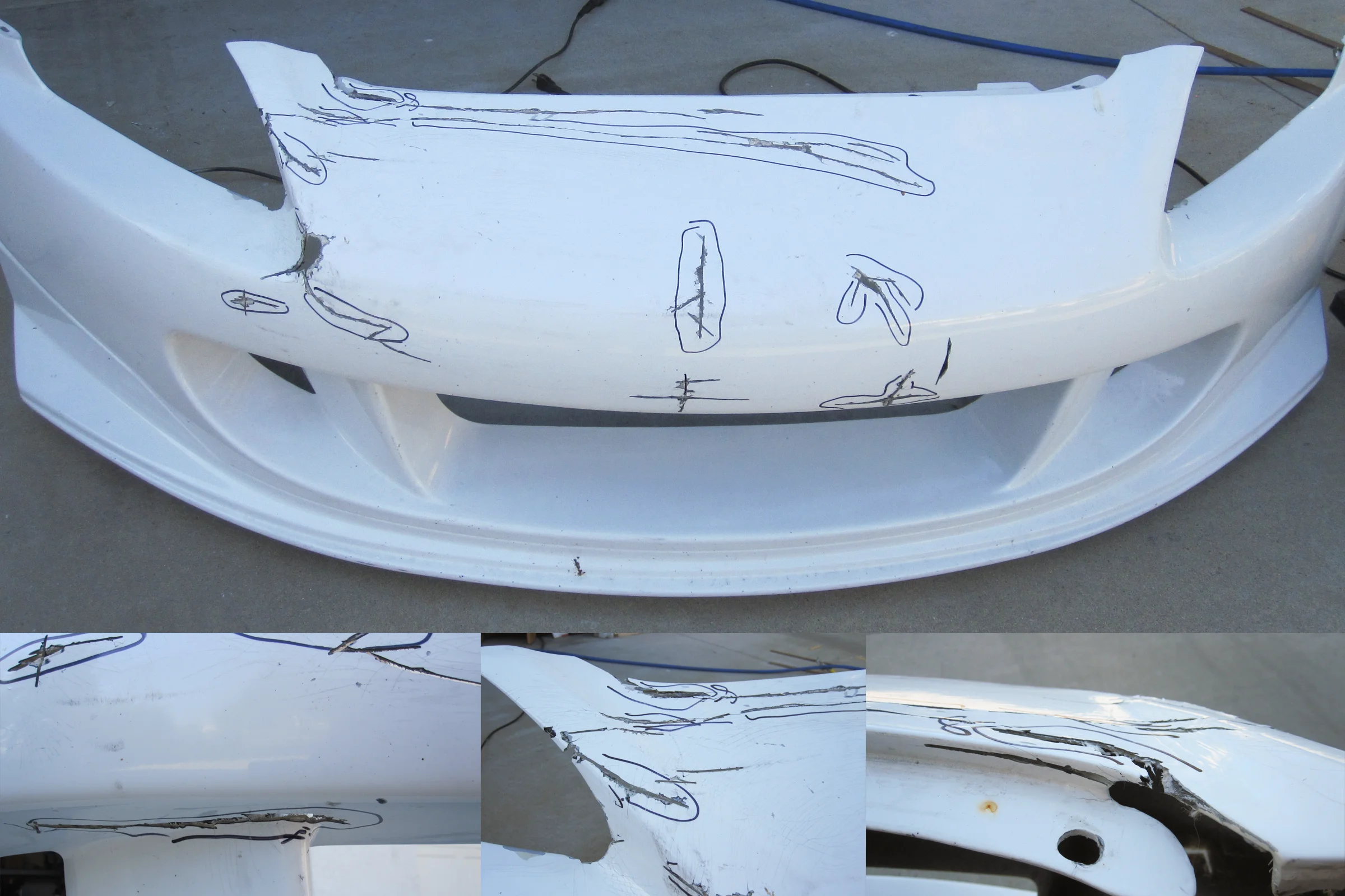
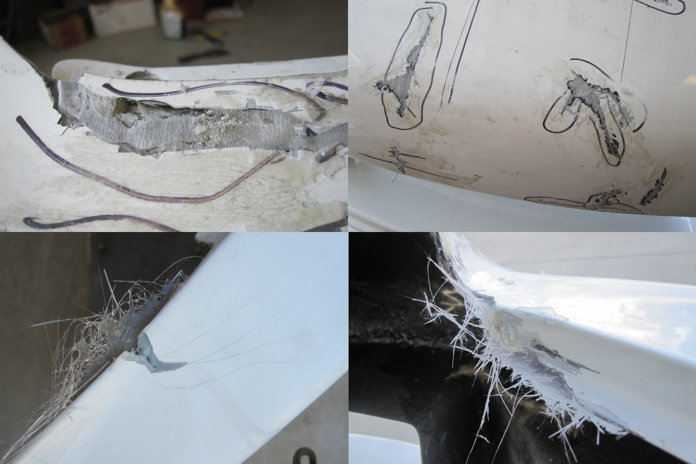
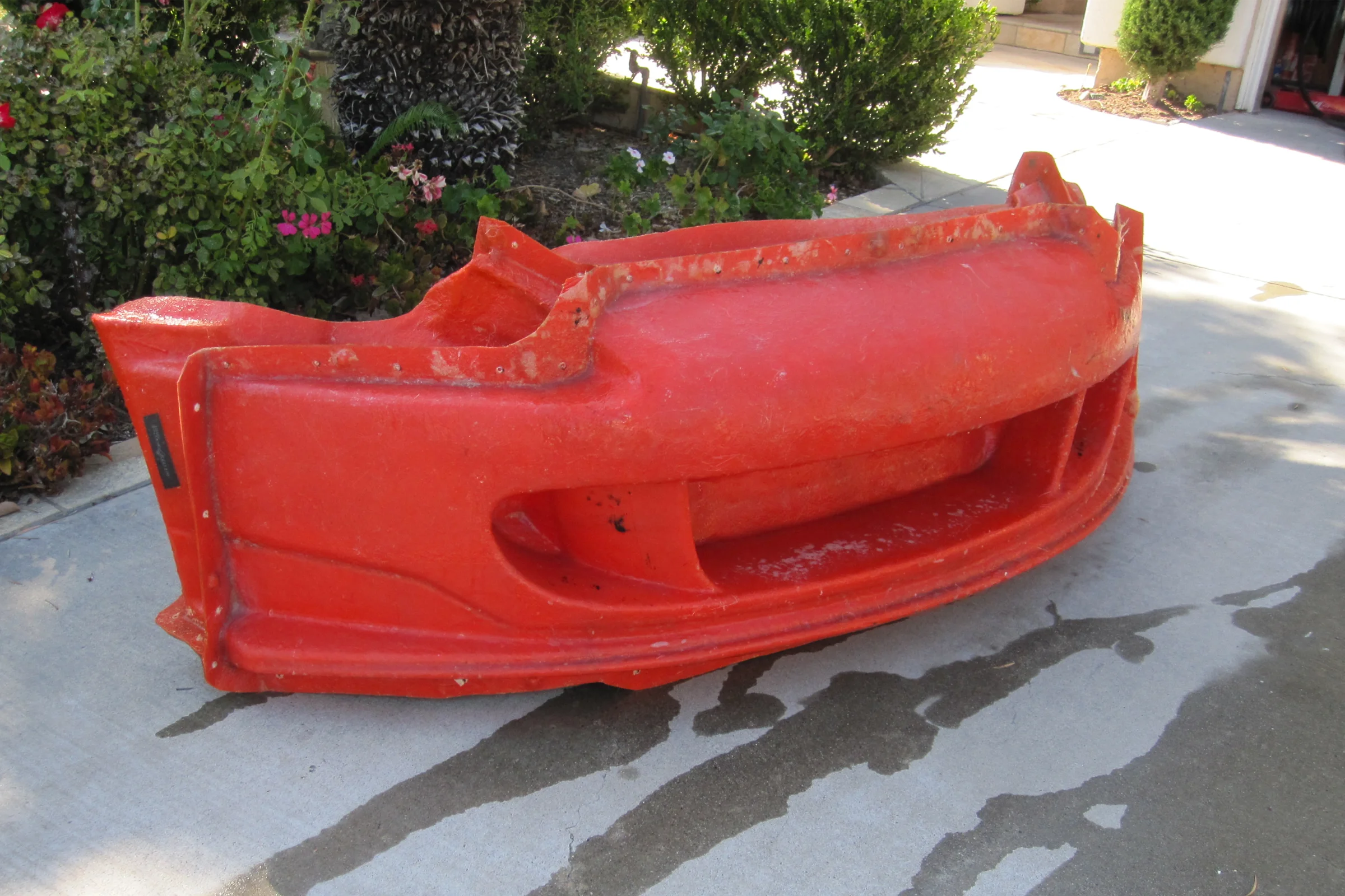
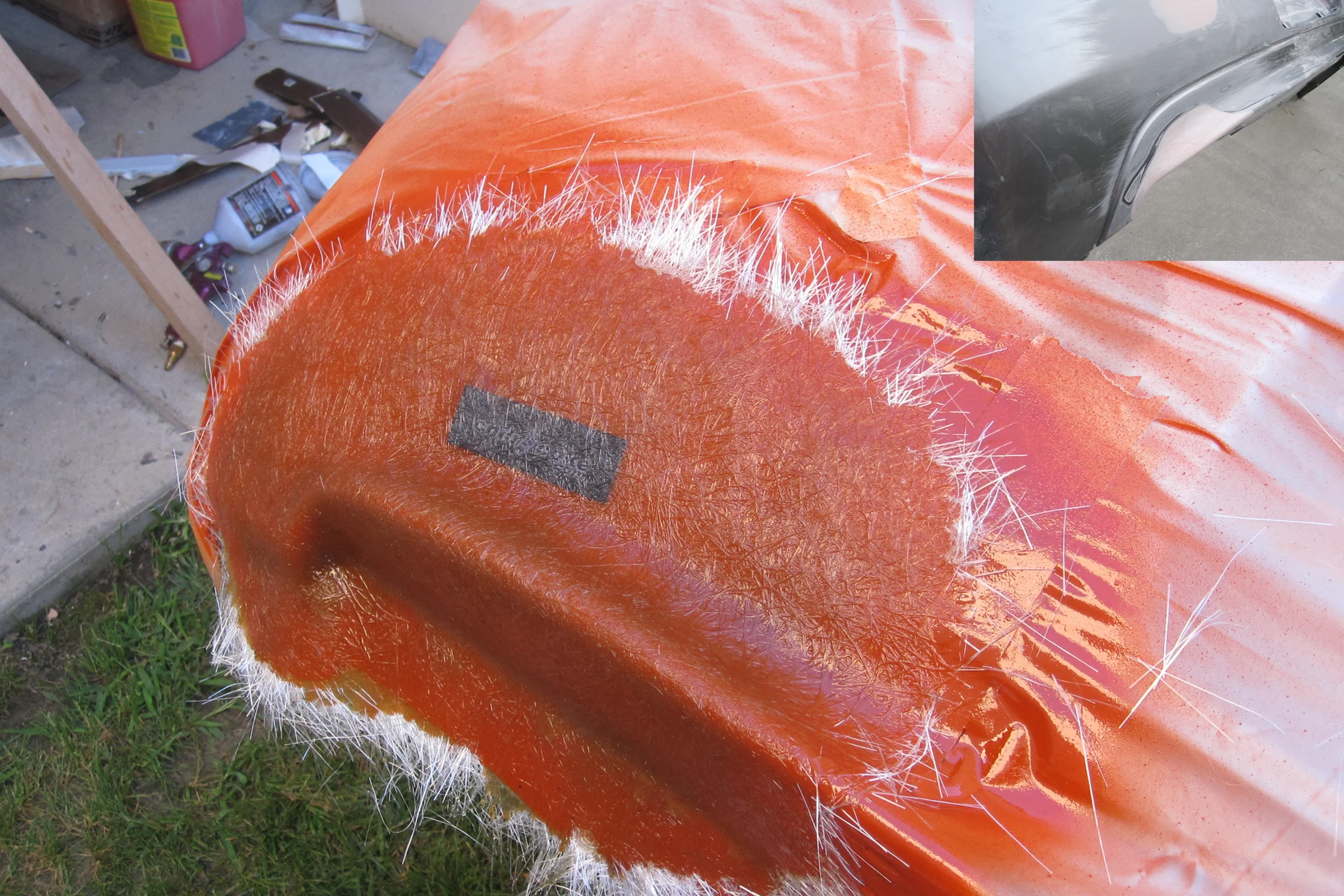
Sourced a damaged $2,000 Japanese tuner bumper to serve as the plug. First task: structural fiberglass repair. Grind the damaged area back to clean material, overlap fresh chopped strand mat and resin, trim and sand back to surface.

What rarely gets documented in car builds is what comes after the repair: fitting the bumper to the car. Aftermarket fiberglass panels don't arrive ready to bolt on. Every edge, every gap, every surface transition against adjacent body panels requires work. Body shops charge significant labor for exactly this, blending fiberglass to factory panel gaps and making it look like it belongs. This was done in the garage, to the same standard, before any mold work touched the bumper. The repair surface also had to be flawless before molding, every imperfection in the plug transfers permanently into every part pulled from it.

Mold section reduction: 9 to 5 parts, parting line engineering detail in Build Depth ↗
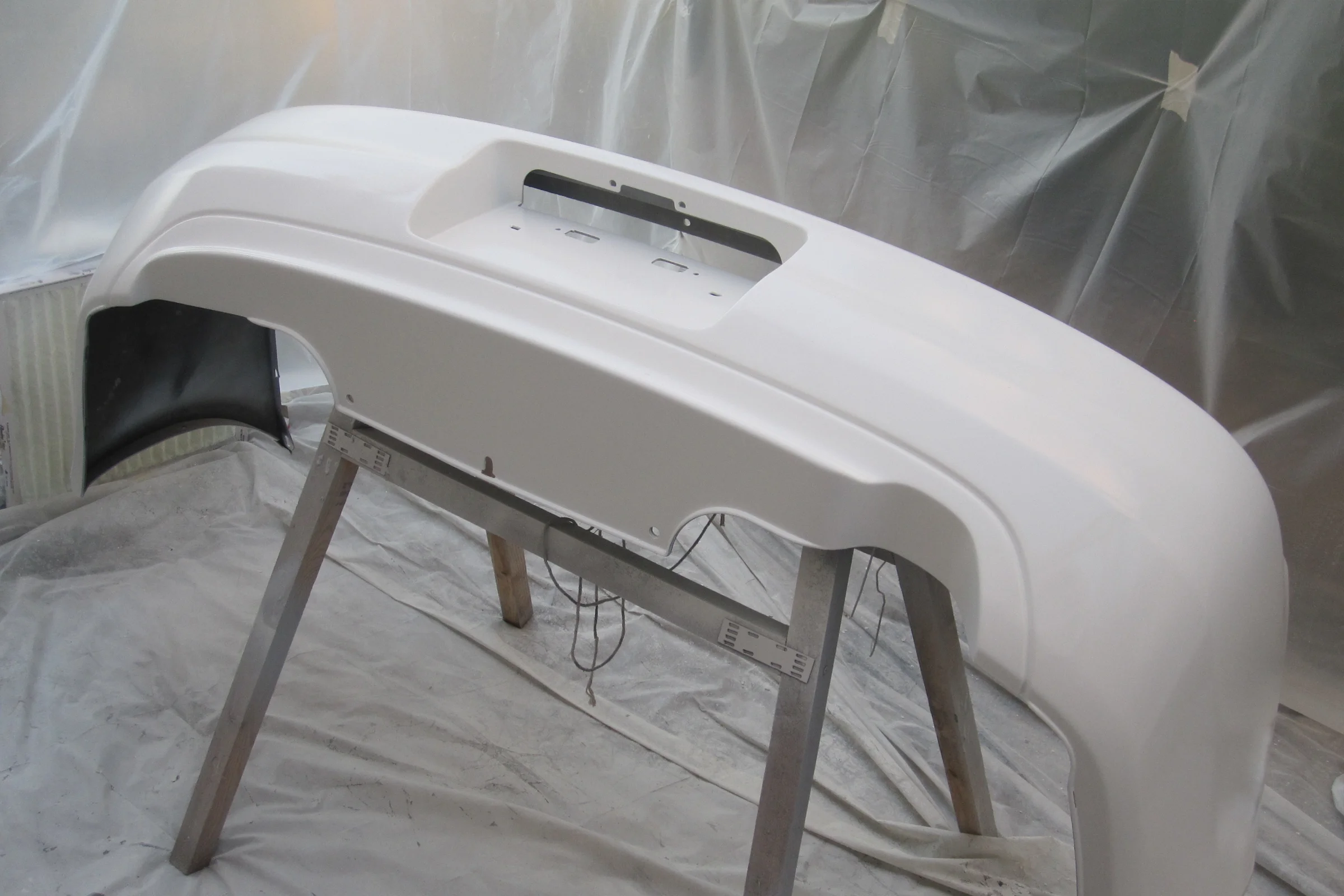
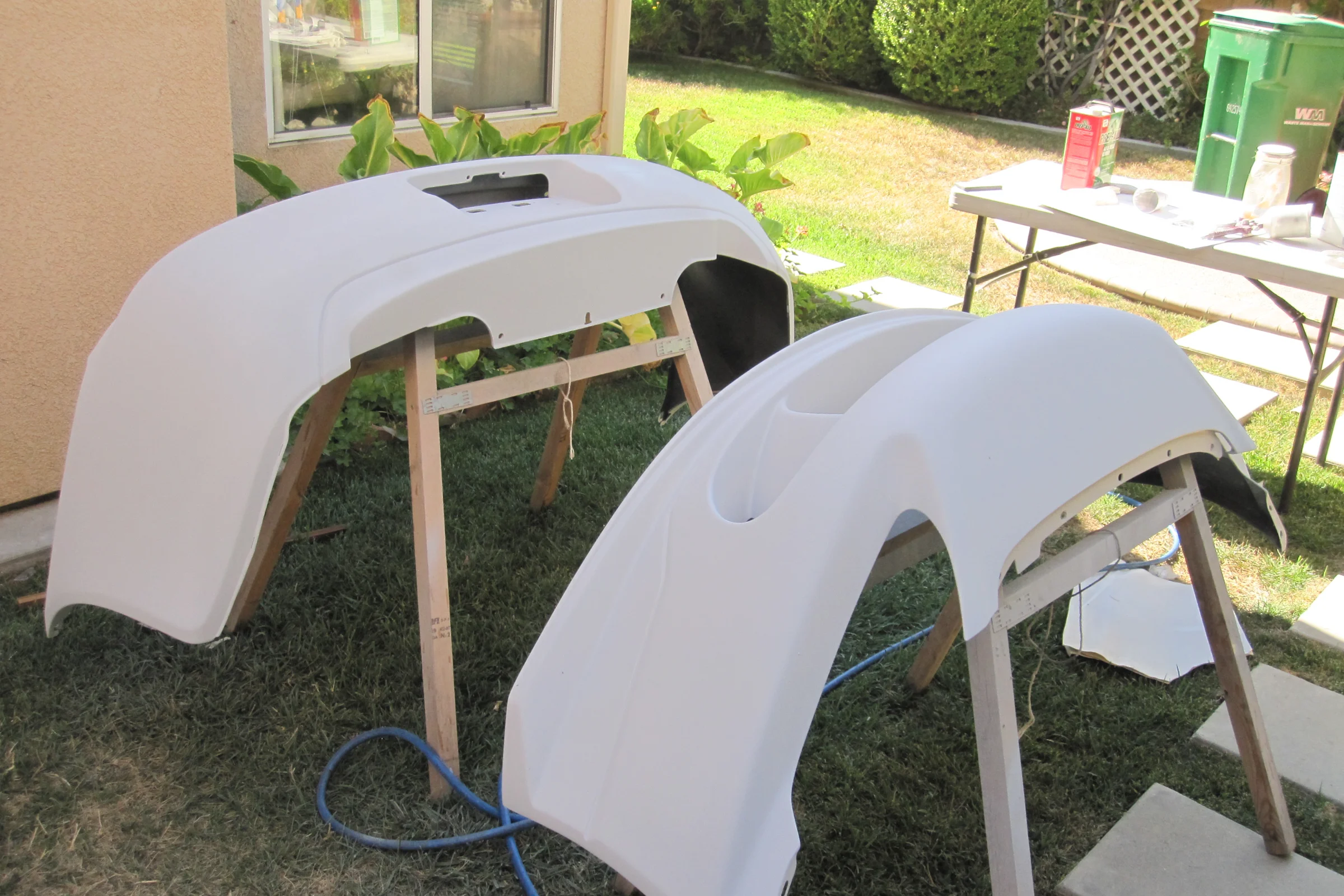
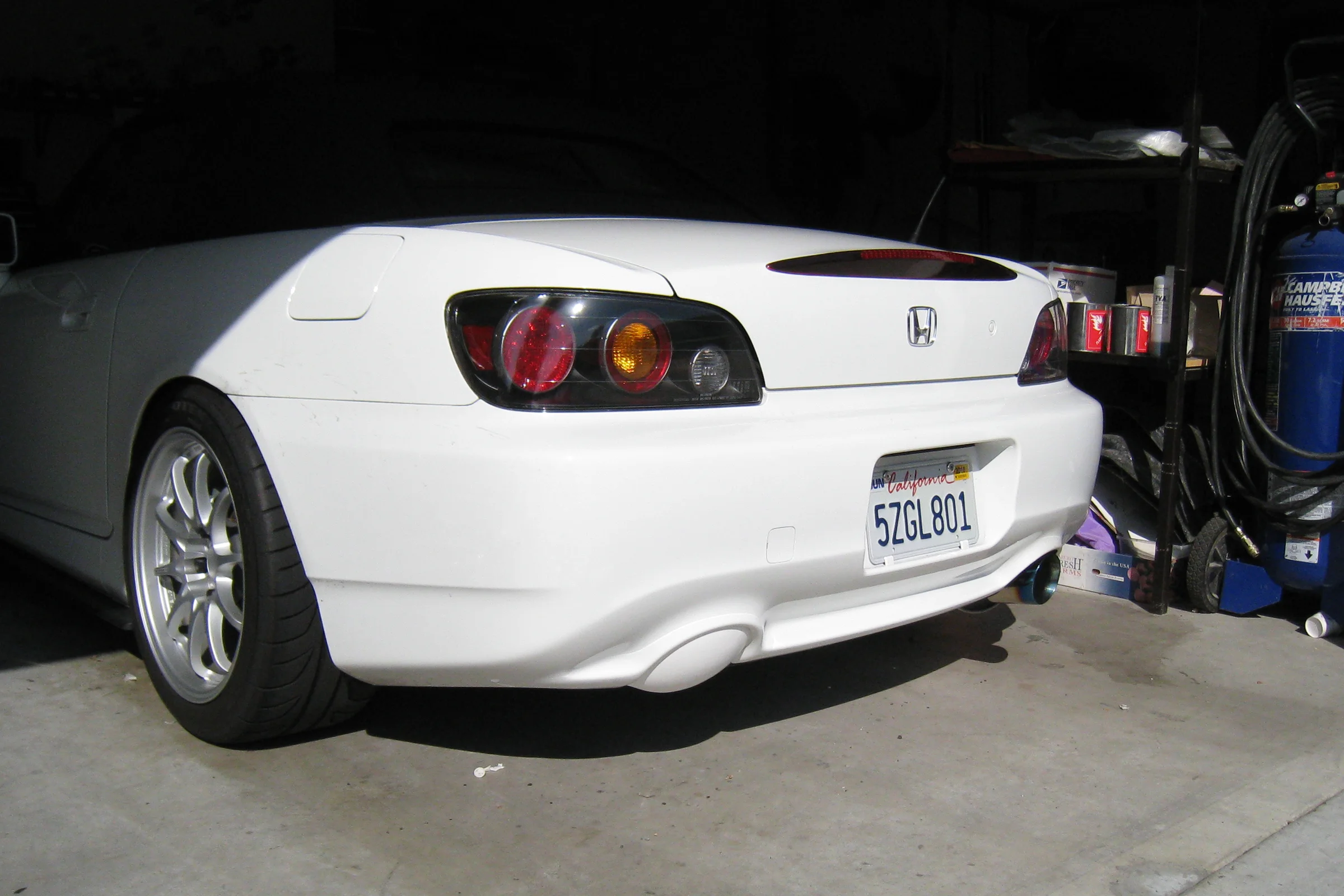
The main mold section was built with the bumper still bolted to the car: reverse-parked into the garage, front jacked up for underside access, garage door opening masked with plastic sheeting to contain gelcoat overspray. A bumper removed from the car flexes under its own weight and will pull a mold that no longer fits when reinstalled. Chipboard flange walls with triangular gussets defined the parting lines. Self-adhesive rubber frustum pads set the registration points. After the first section cured, the bumper came off the car with the mold section still attached, moved to sawhorses, and the remaining four sections were completed one by one off the car. Two smaller molds covered the separate air guide inserts.
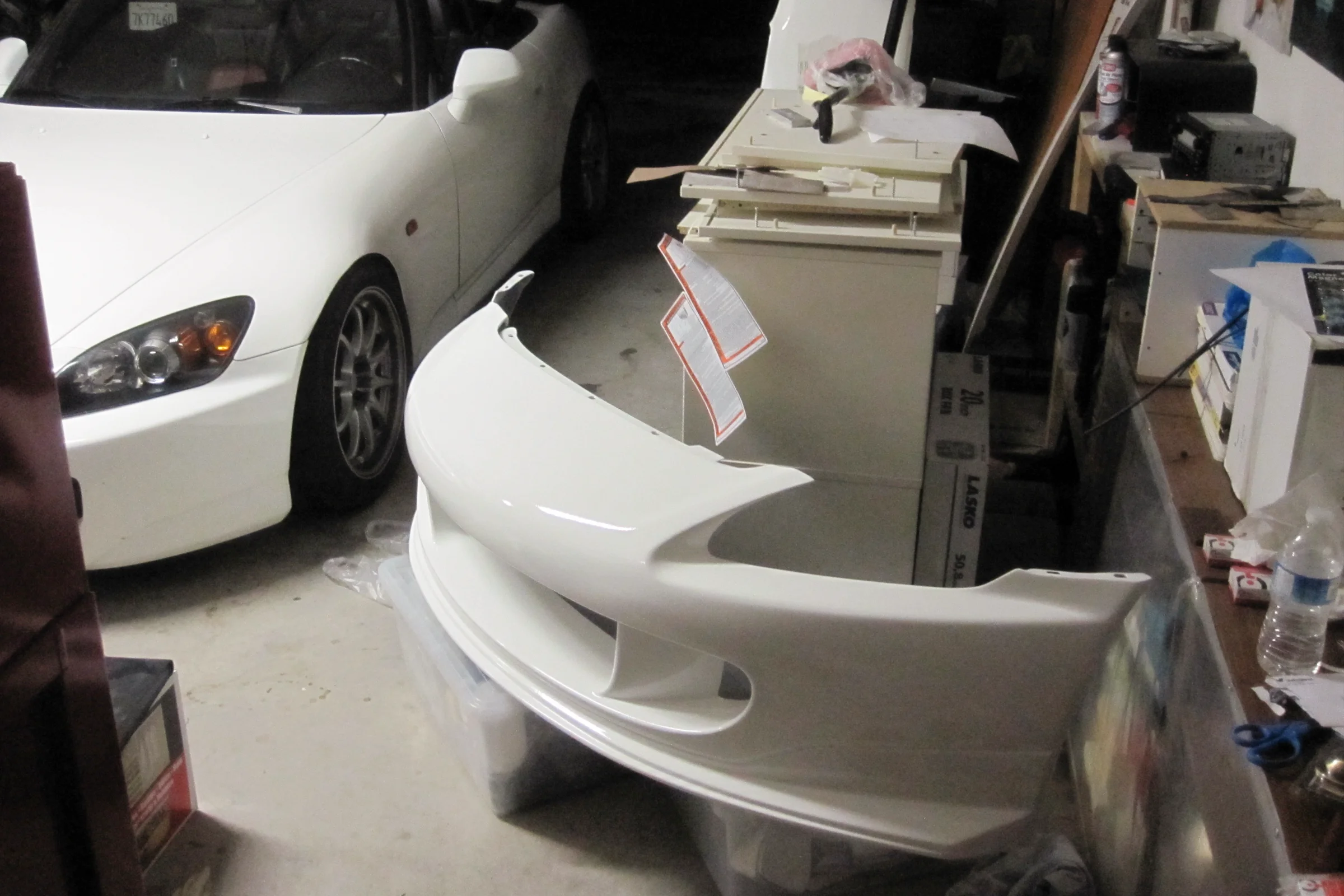
The first test pull fit the car without any correction work, because all the fitting had already been done on the repaired bumper before molding. The mold simply copied what was already correct.
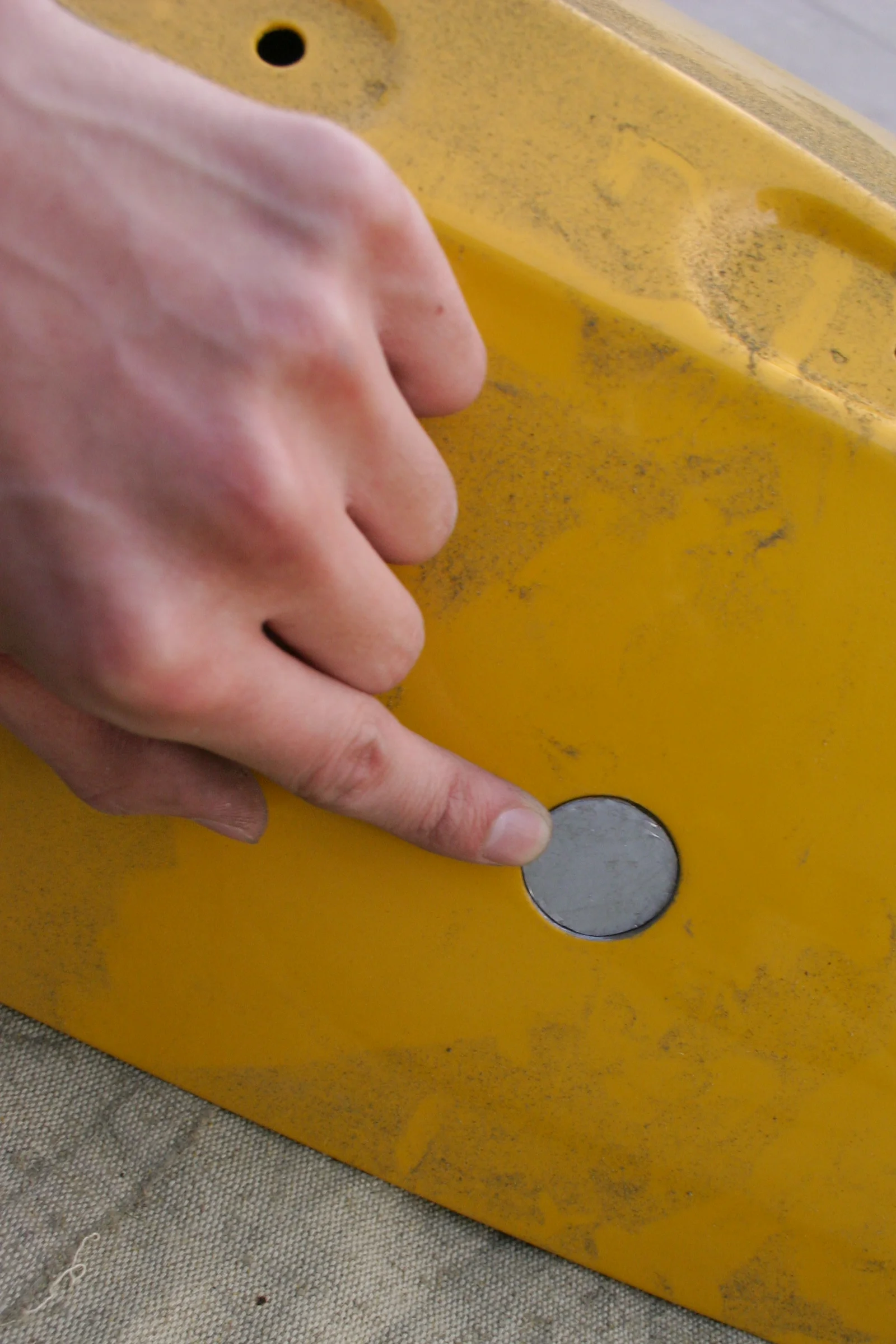
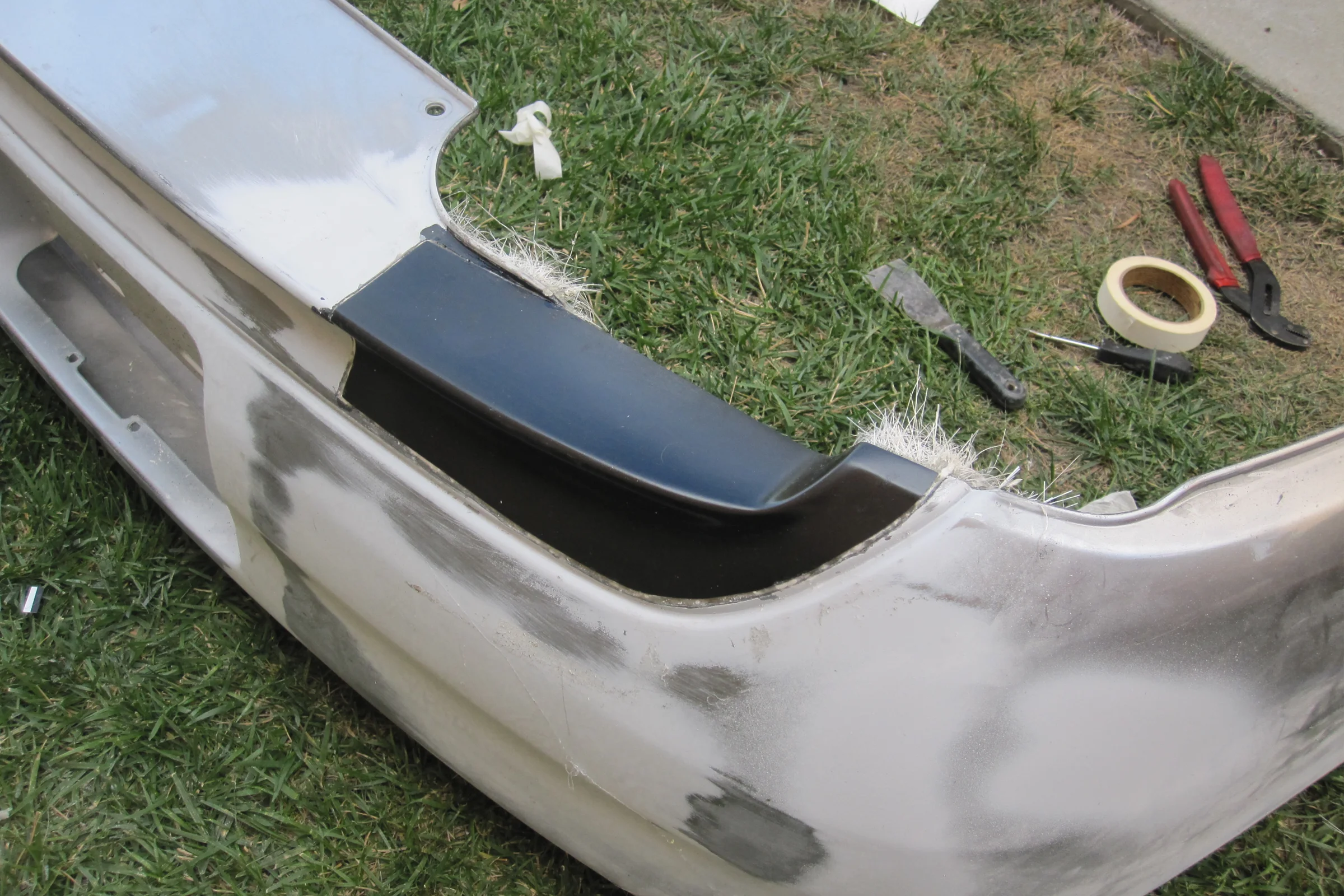
AP1 Exhaust Mod and Backyard Paint Booth
The AP1 rear bumper also needed a single exhaust conversion. The AP1 exhaust cutout is smaller and less visible than the AP2, so a snap-on cover was not the right approach. Instead: the opening was filled with wood and body filler, hand-shaped to match the surrounding body lines, and a small mold was pulled from the filled area. An oversized fiberglass panel was made from that mold, the filler block cut out of the bumper, and the new panel fiberglass-bonded into the opening from behind. Hand-sanded until the transition disappeared into the surrounding surface.

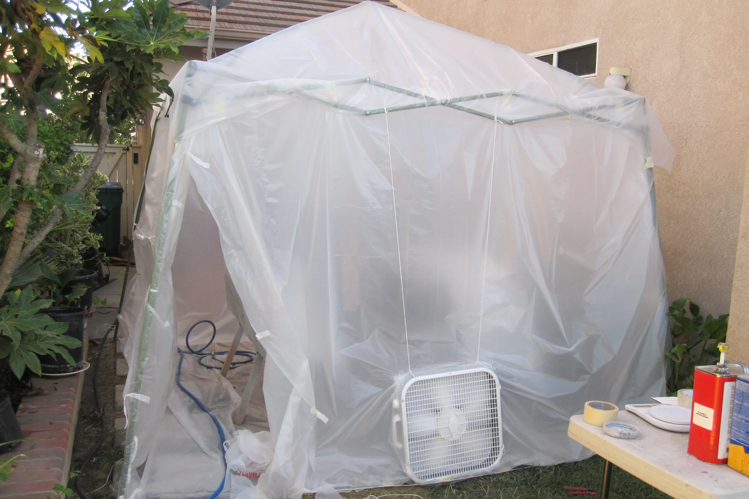
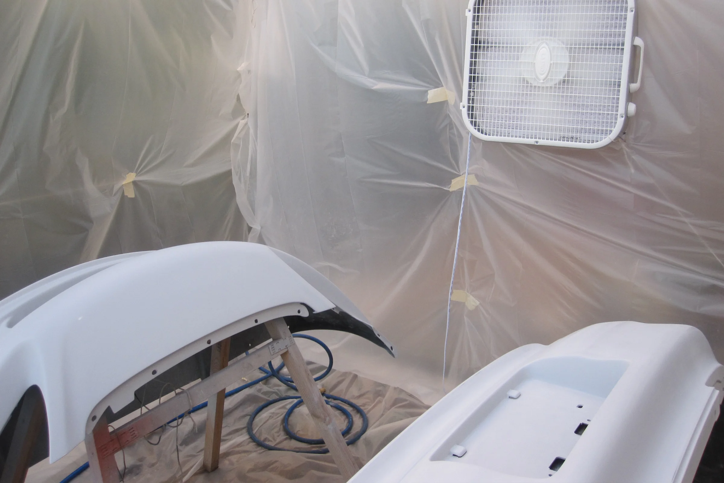
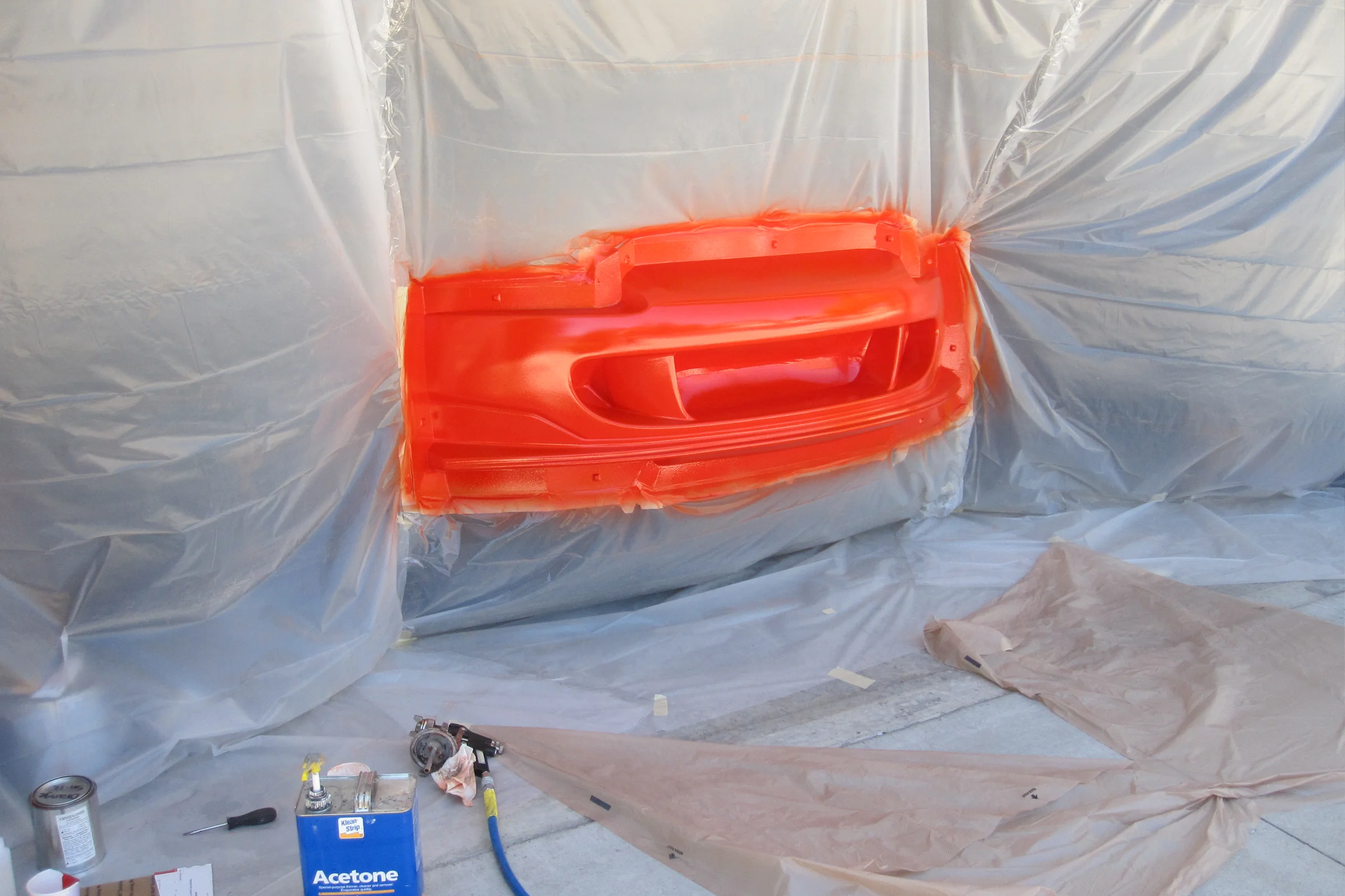
With both the Amuse front bumper and the AP1 rear bumper ready for paint, a booth was built in the backyard. Canopy tent, plastic tarp walls, box fans with AC filters serving as both intake air filtration and exhaust paint trap before air is vented out. Setup took two hours. High build primer, sealer, color-matched PPG professional automotive paint, and clear, all shot with a cheap Harbor Freight HVLP gun. Block-sanded between coats. Minimal orange peel, wet look off the gun and only needed a light wet sand before polish. Nobody could identify it as anything other than a professional booth job. The total cost of the booth hardware was less than one hour of body shop labor.