Suspension
Geometry
Correction
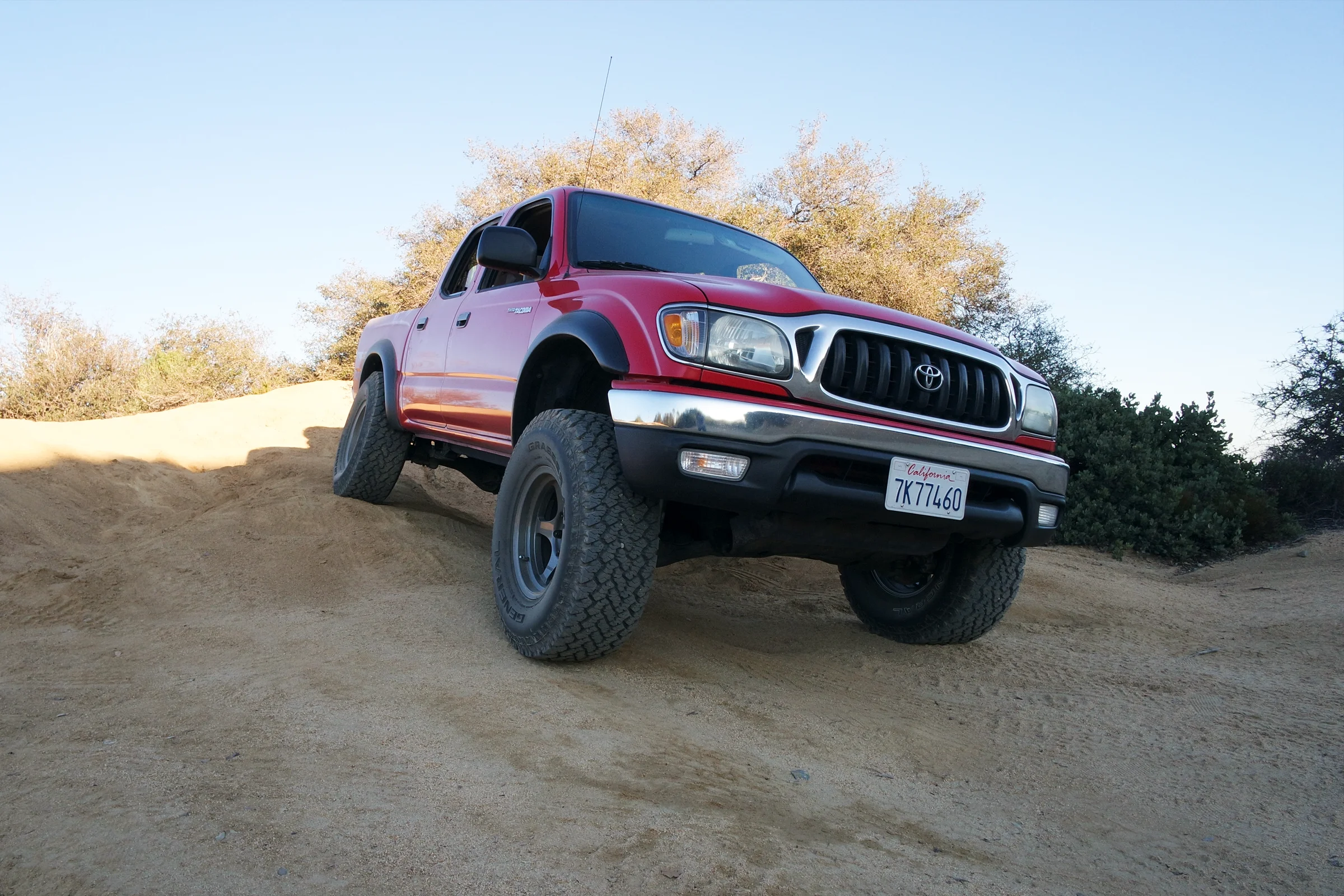
Lifted the Tacoma 3 inches. The steering wheel stopped self-centering. Aftermarket upper control arms were $1,000. Instead: modeled the factory suspension geometry in SolidWorks, calculated the correction delta, machined a custom fixture to hold the irregularly shaped arm on the mill, turned new ball joint tapered couplings on the lathe, and had the modification TIG welded. Alignment shop achieved factory spec on the first attempt with every adjustment bolt centered in its range.
The Geometry Problem
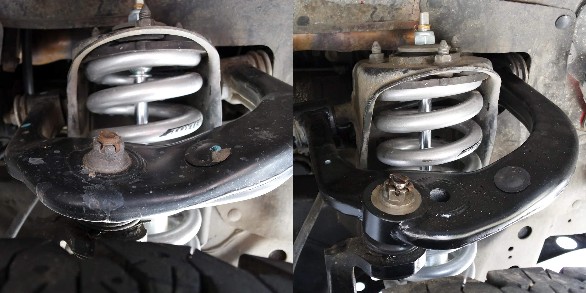
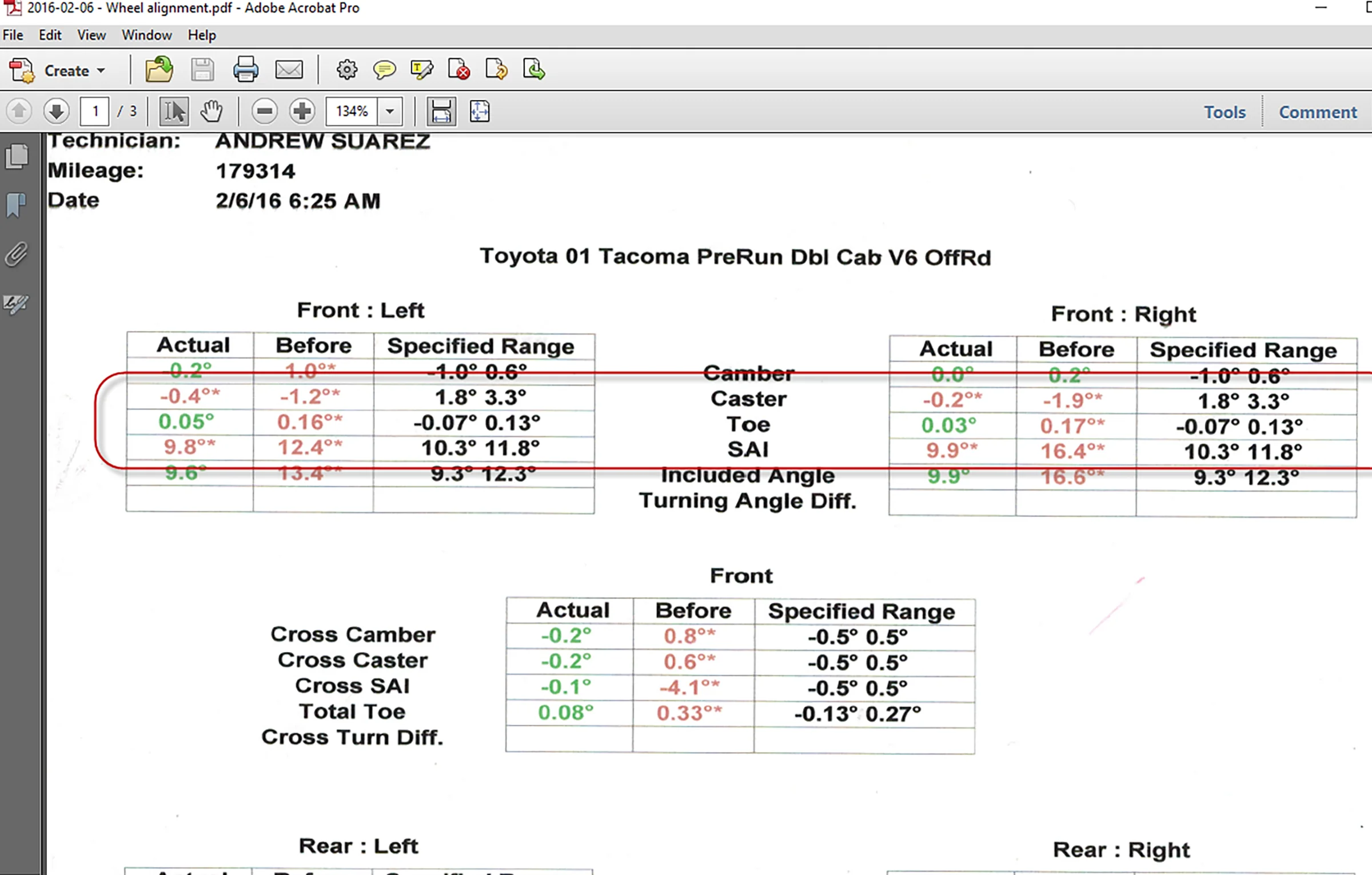
After the 3-inch lift, at highway speeds tracking was normal. The abnormality appeared only during low-speed, high-lock maneuvers. The steering wheel lacked any self-centering moment after a U-turn and required manual input to return to zero. I drew from my S2000 suspension tuning experience to visualize the kinematic shift and identify the caster deficiency. A 3-inch lift had pushed the upper ball joint too far forward relative to the lower, neutering the steering feedback. A four-wheel alignment confirmed the theory. The technician found caster angle significantly out of spec with every adjustment bolt maxed at its limit. The system could not be brought back to factory specifications without mechanical intervention.
The standard commercial solution is aftermarket upper control arms designed with geometry correction built in, typically $1,000 for a pair. The factory upper control arm is two pieces of heavy-gauge stamped steel welded together, with a ball joint mount welded in between. The geometry correction needed was a repositioned ball joint mount. A machined component problem, not a reason to buy new arms.
SolidWorks Geometry Model and Correction Delta
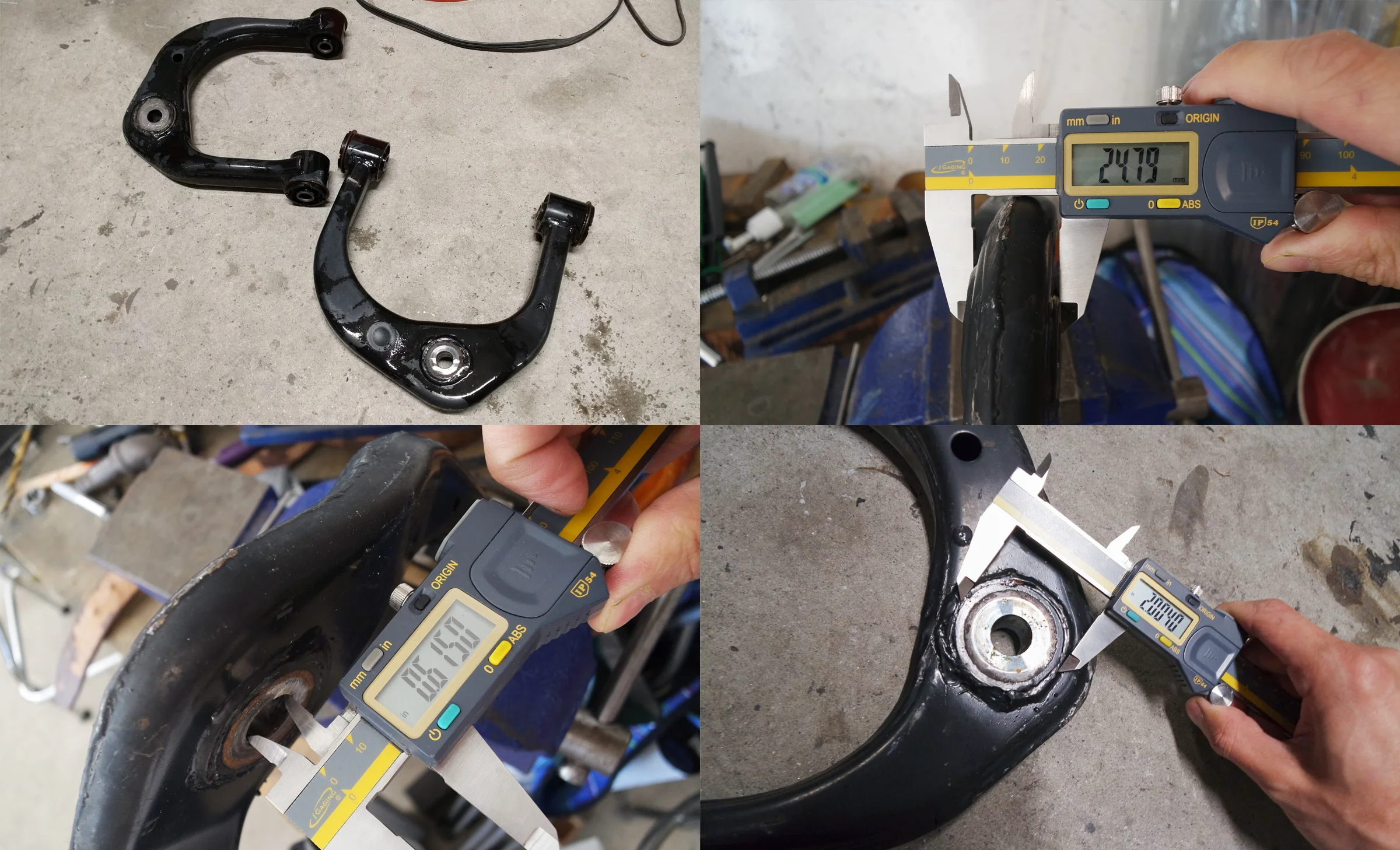
Factory upper control arms are essentially worthless once a truck is lifted. Every owner replaces them with aftermarket units. A free pair was available almost immediately. Measured all the critical geometry: arm length, ball joint position and taper angle, frame mounting pivot locations, caster angle at stock ride height. Plotted everything in SolidWorks as a 2D suspension geometry model. Simulated the geometry at stock height, then adjusted the model to show 3 inches of lift and its effect on the upper arm's effective position relative to the lower control arm and steering axis.
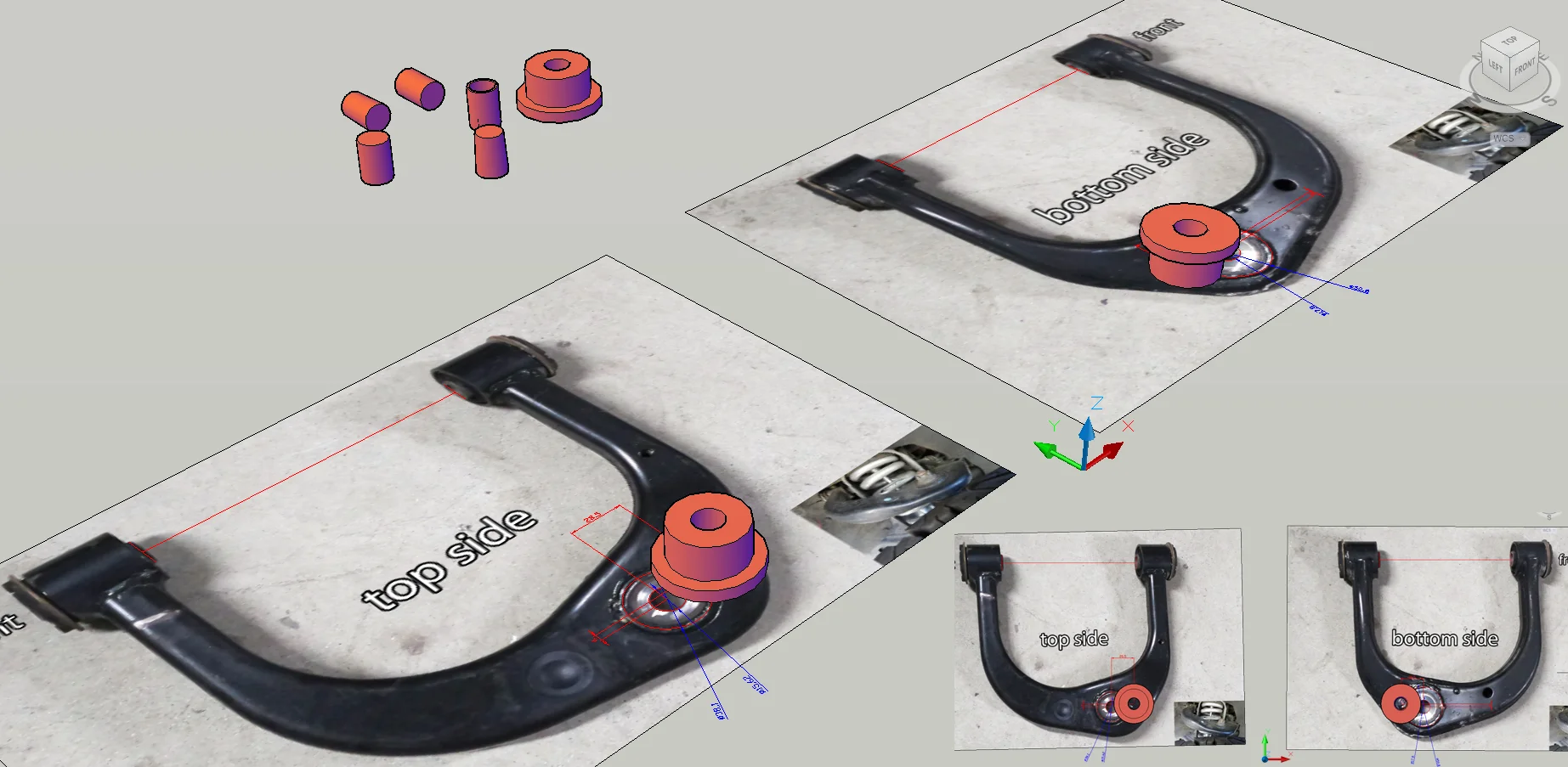
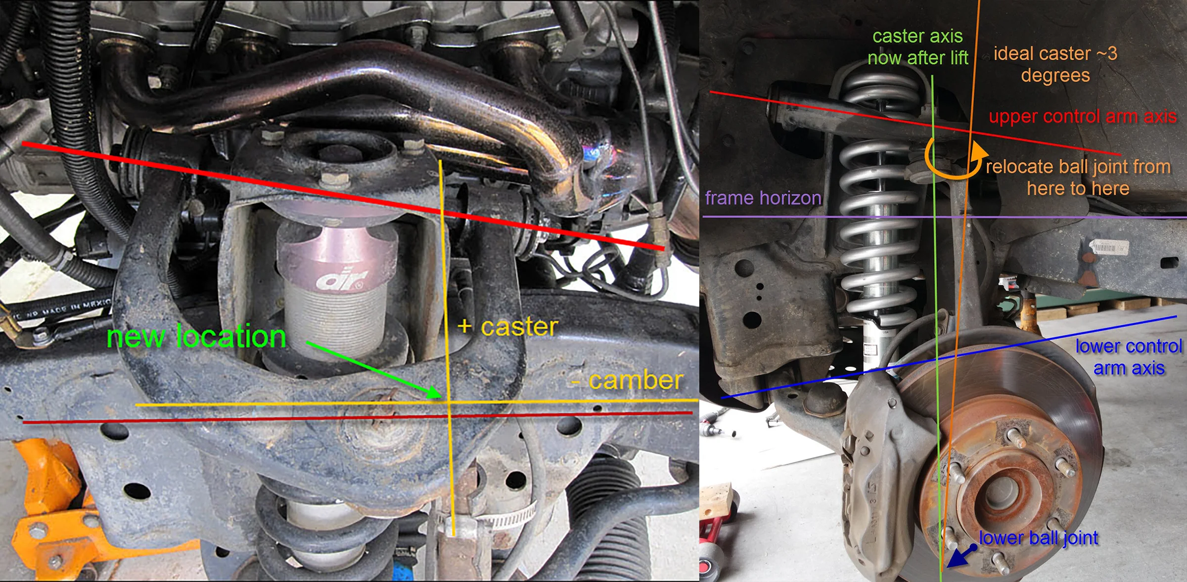
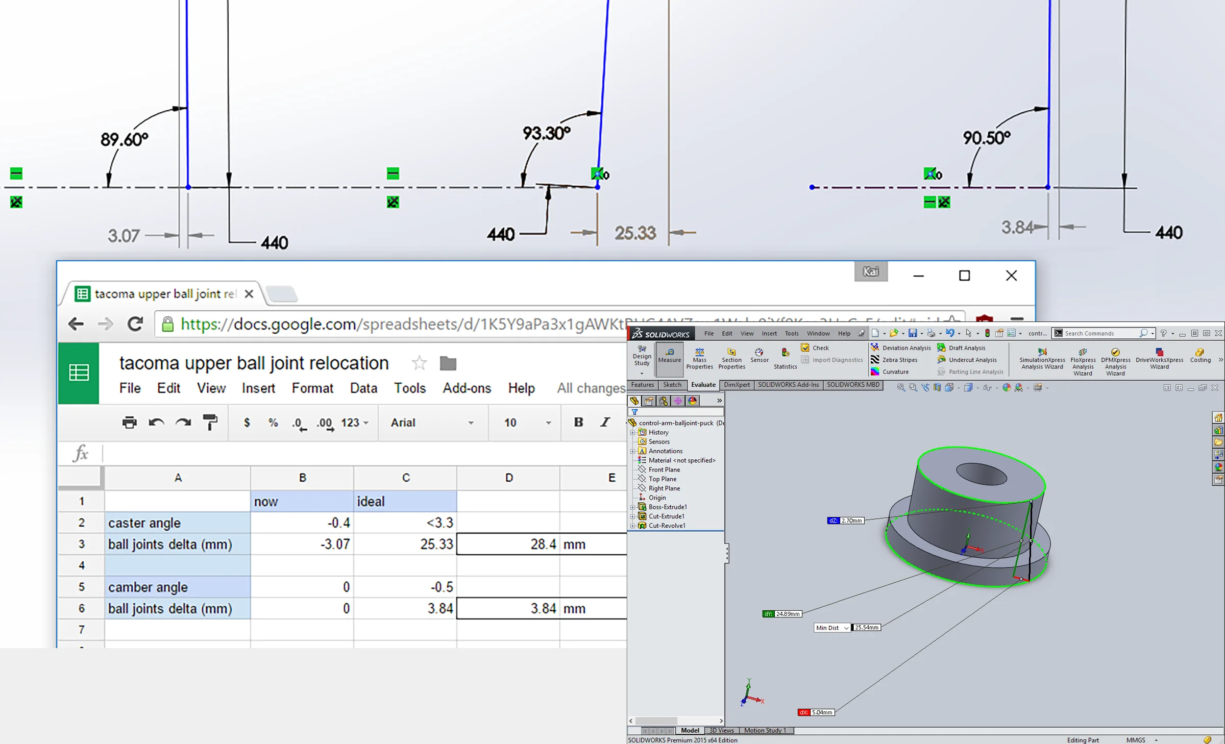
The model made the correction delta visible and calculable: a specific angular offset of the ball joint mount from the factory arm geometry that would restore caster to factory spec at the lifted ride height. Verified the result with a spreadsheet that independently calculated the caster change from the geometric inputs. Both methods agreed. The corrected ball joint position was within the footprint of the factory arm. There was enough material in the stamped steel arm to pocket in a new mount without compromising structural integrity.
Material and Structural Verification
Before any material was removed from the factory arm, the structural context and material were characterized independently. In a double wishbone suspension, the upper control arm carries primarily compressive loads. The lower control arm and its chassis mounts form the primary structural load path; the upper arm's role is to maintain geometry and react the comparatively lighter loads at the top of the knuckle. That load case makes modification a tractable problem — but it is not a reason to skip verification.
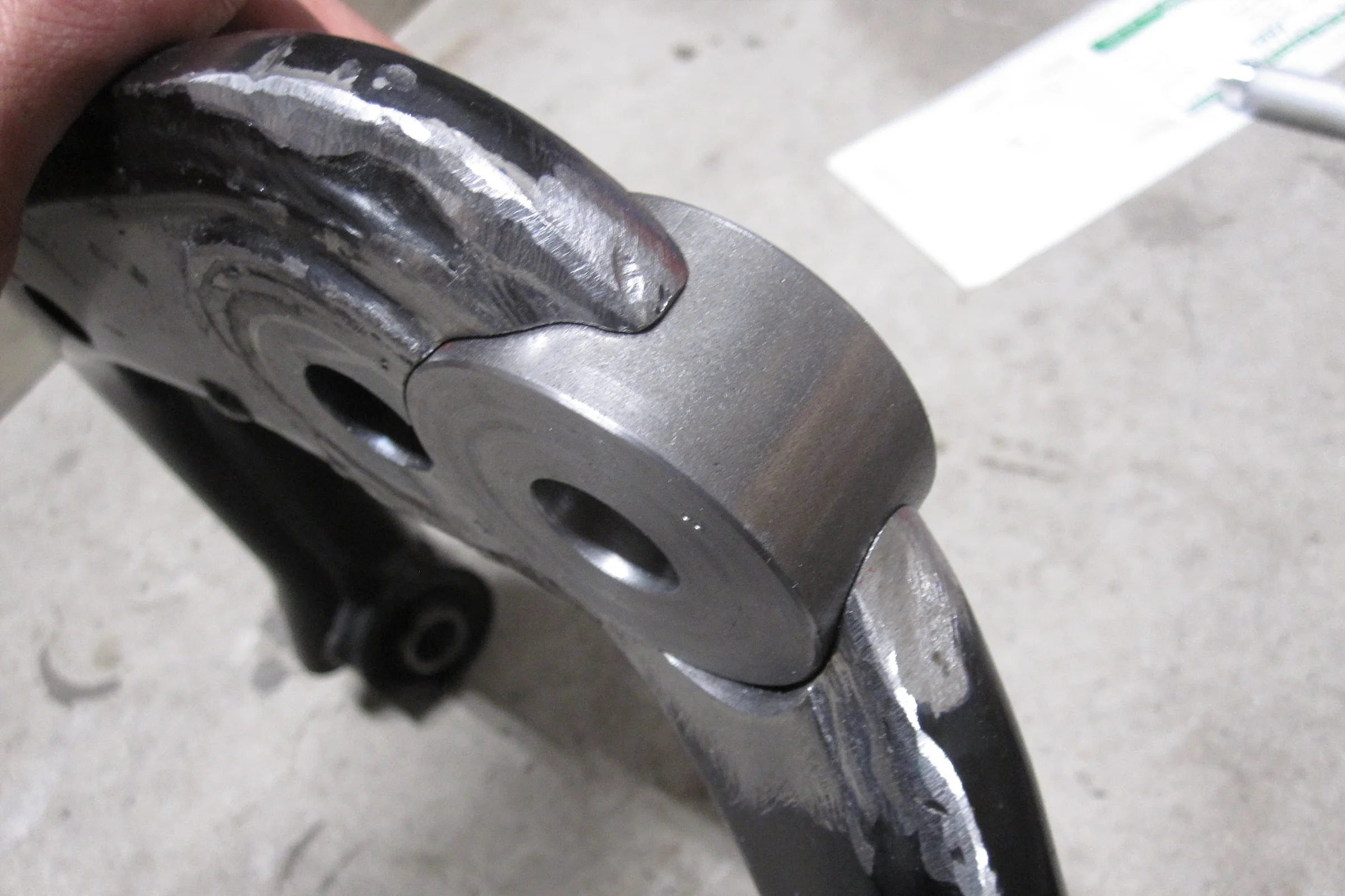
The factory arm construction was readable from the outside: two stamped steel halves forming upper and lower profiles, joined along a visible weld flange, with a turned tapered ball joint stub welded into the arm end. Material hardness was verified with a center punch against the arm and against a known piece of mild steel scrap side by side. The indentations matched across both the stamped halves and the turned stub — consistent with mild steel, and distinguishable from significantly harder alloy or heat-treated material. Both observations were independently confirmed during machining: chip formation, color, and cutting force during the pocket mill all behaved consistently with mild steel, and the open pocket gave a direct cross-section view of the arm wall at the cut face. The welder confirmed the same material behavior during TIG. Four independent checks before and during fabrication, each consistent.
Multiple aftermarket upper control arms from several vendors were also physically inspected before committing to this approach. Most consisted of simple bent tubing sections with basic gussets. Several appeared to be of equal or lesser construction quality compared to the factory stamped steel arms. The aftermarket option was deprioritized not primarily because of cost — but because the factory arm construction was sound, the material verified across multiple independent checks, and the modification geometrically precise with an alignment shop validation built in as the final confirmation step.
Fabrication: Fixture, Lathe, Mill, Weld
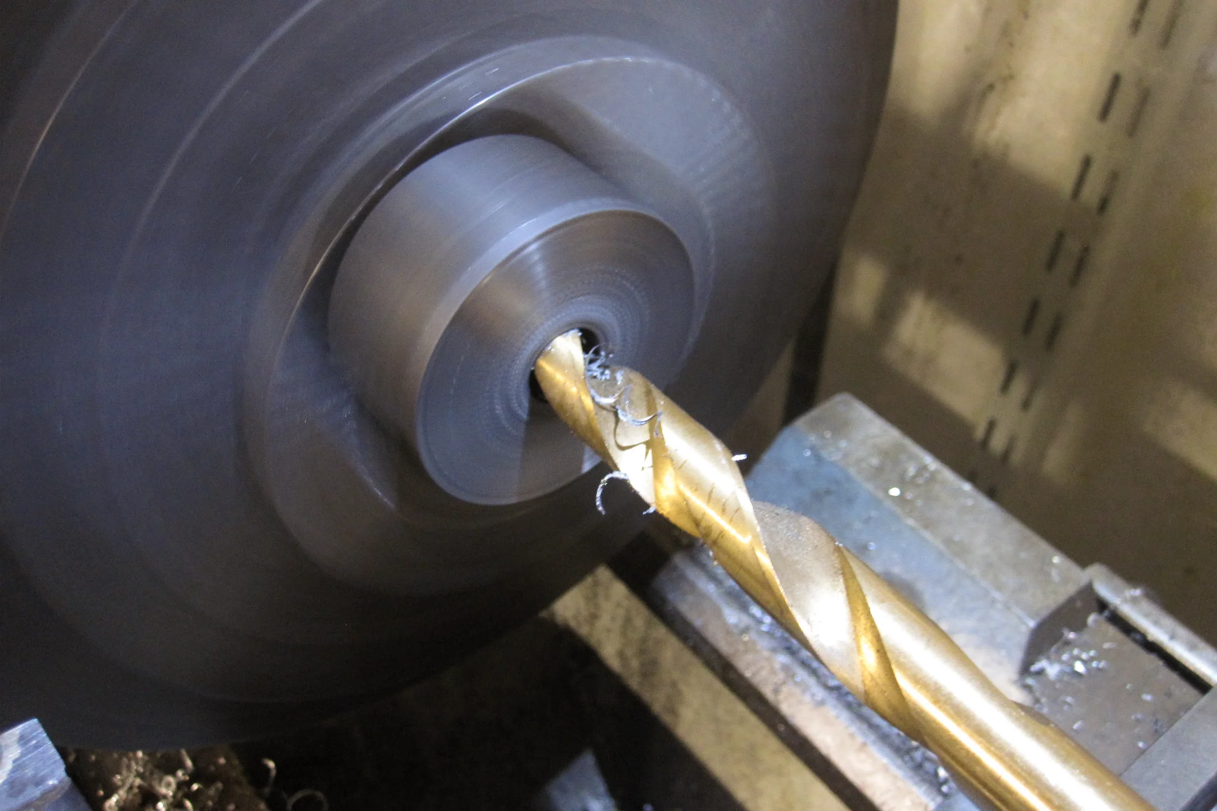
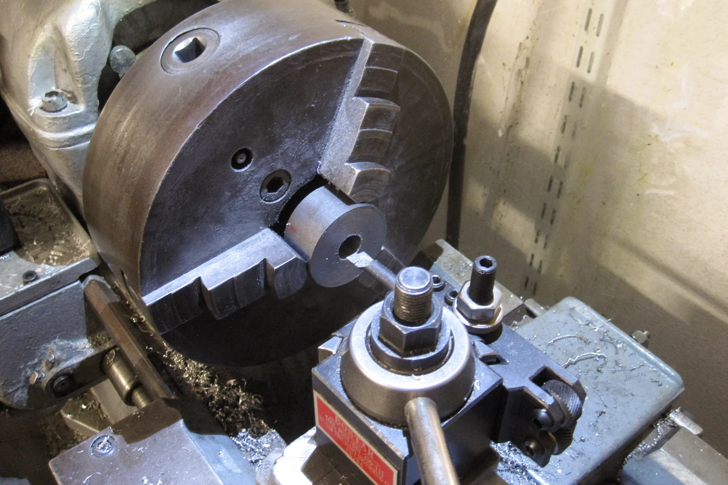
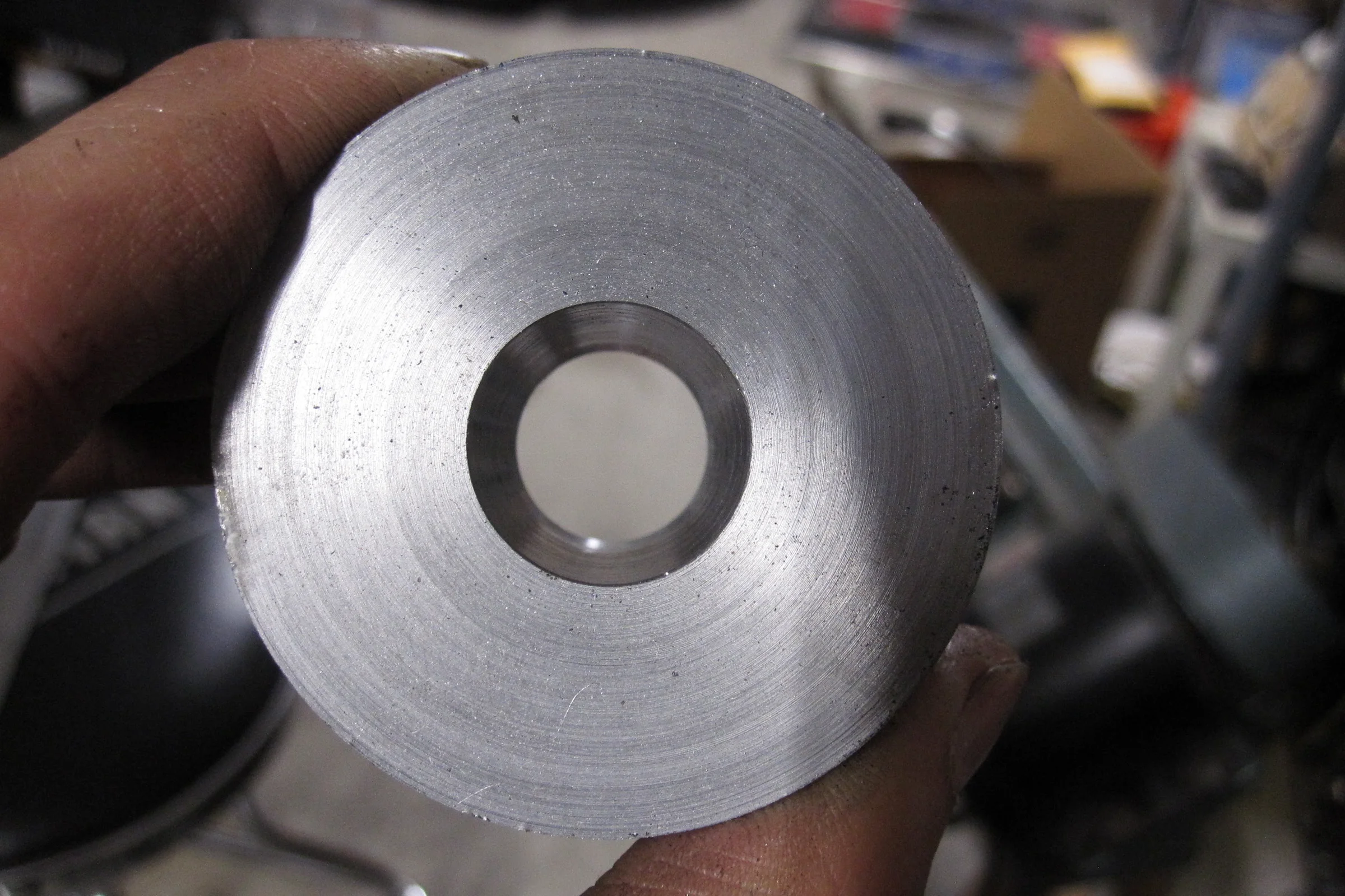
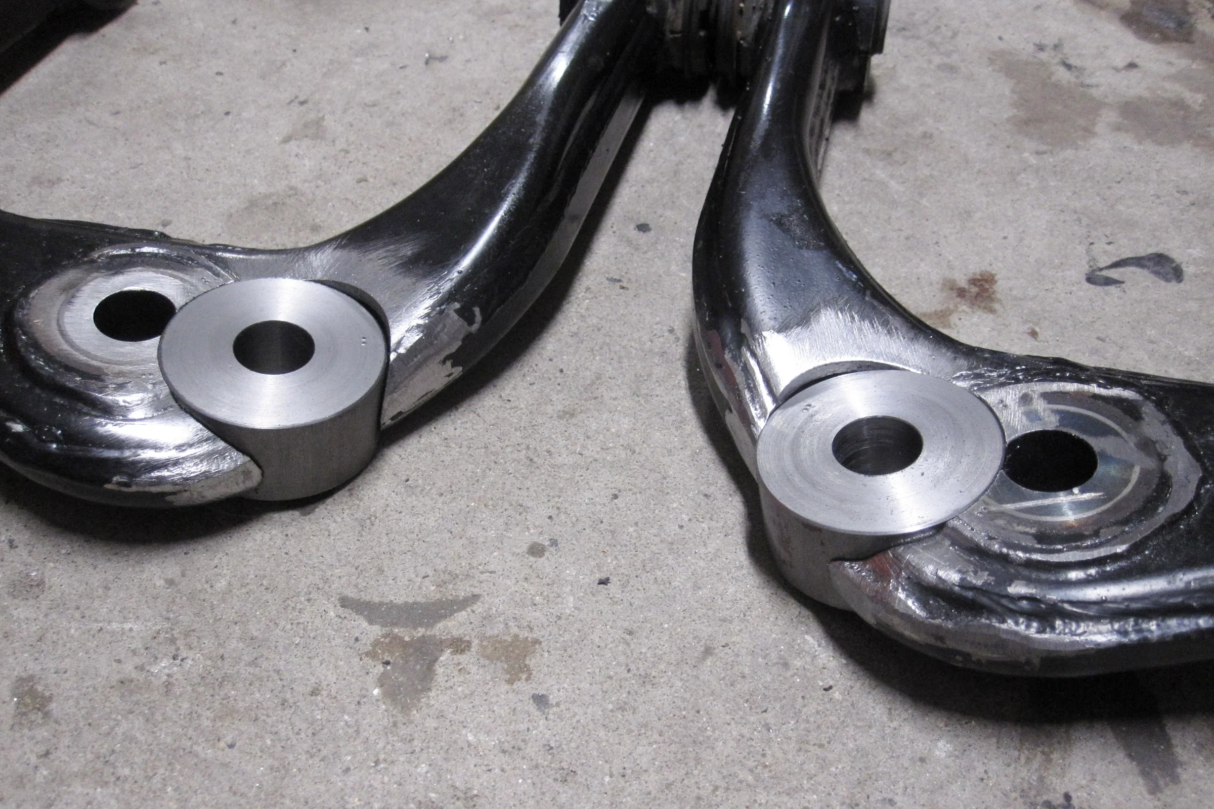
The ball joint mount needed to be turned on the lathe to produce the correct taper for proper fitment. That part was straightforward: turned from mild steel bar stock to my calculated dimensions, taper angle matched to factory spec using the compound slide on the lathe.
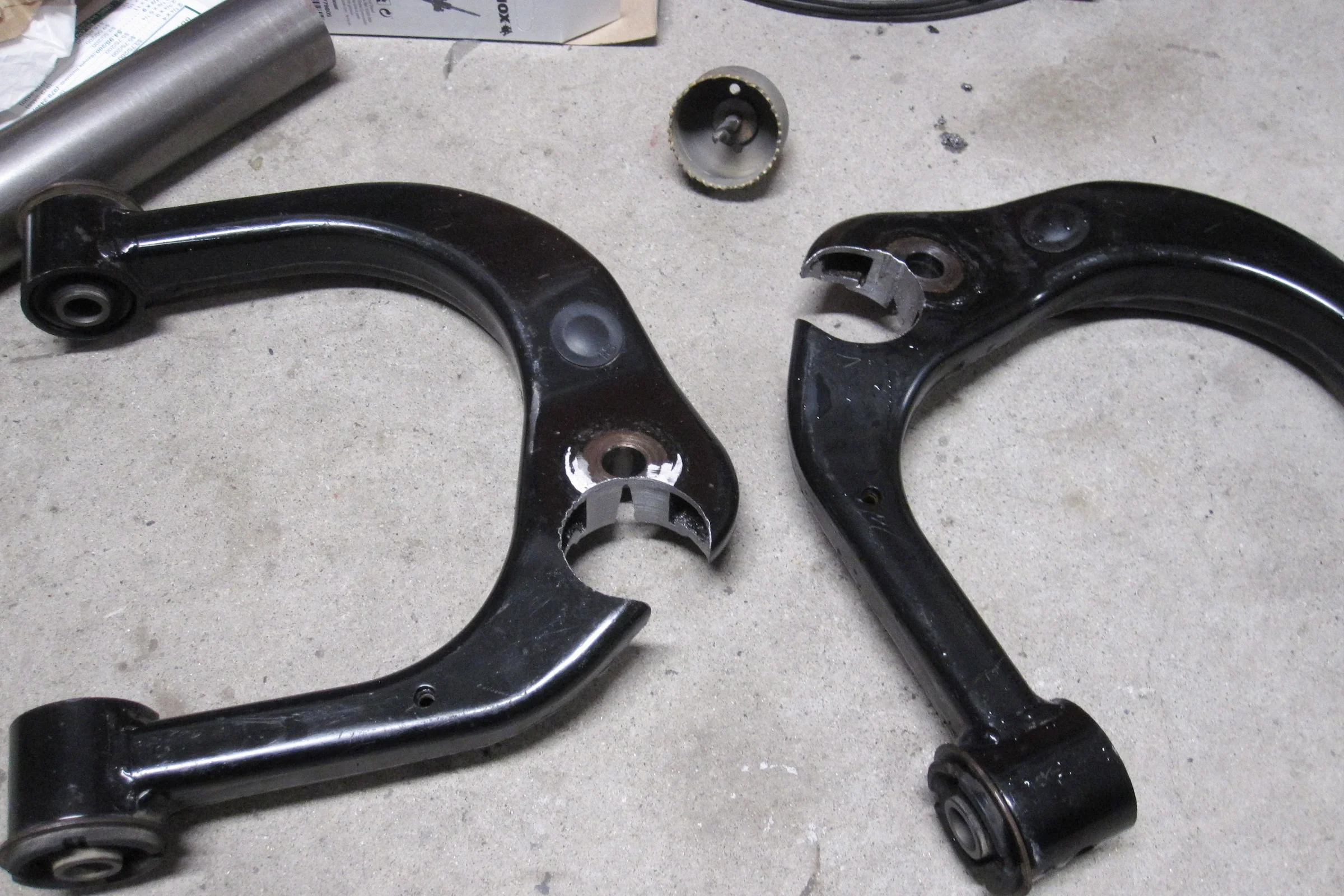
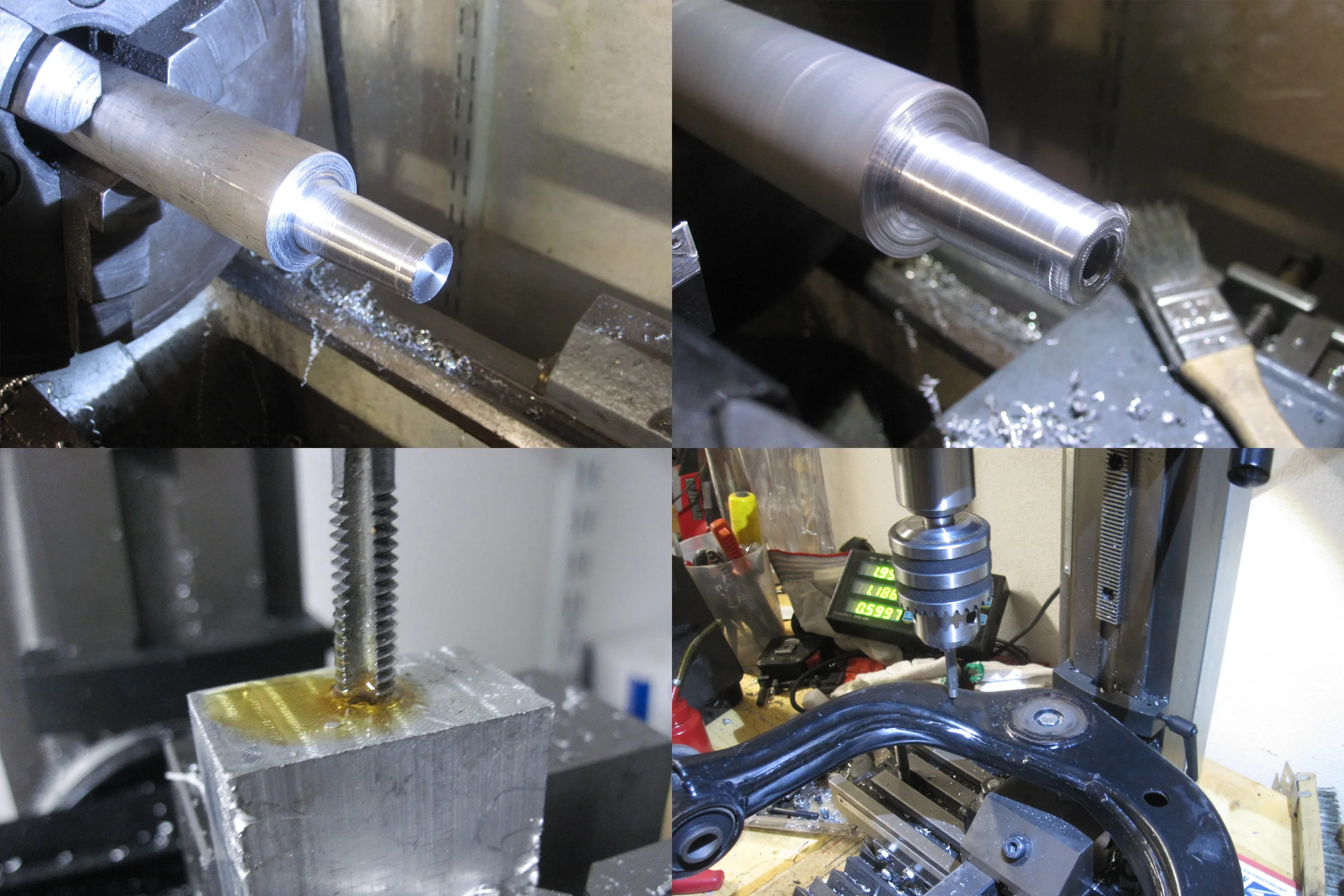

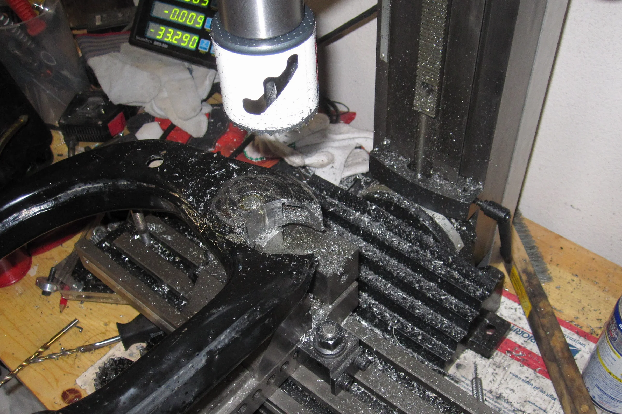
The harder problem was milling the pocket in the factory arm. The upper control arm is an irregular curved shape, essentially impossible to clamp flat on a milling table without the geometry being completely wrong. Before touching the arm, I designed and machined a custom holding fixture that clamped the arm at the specific compound angle needed to orient the pocket face perpendicular to the spindle. Without the fixture, the pocket geometry would have been wrong regardless of how carefully the mill was set up. With the fixture, the mill could cut the pocket at exactly the calculated angle in a single setup.
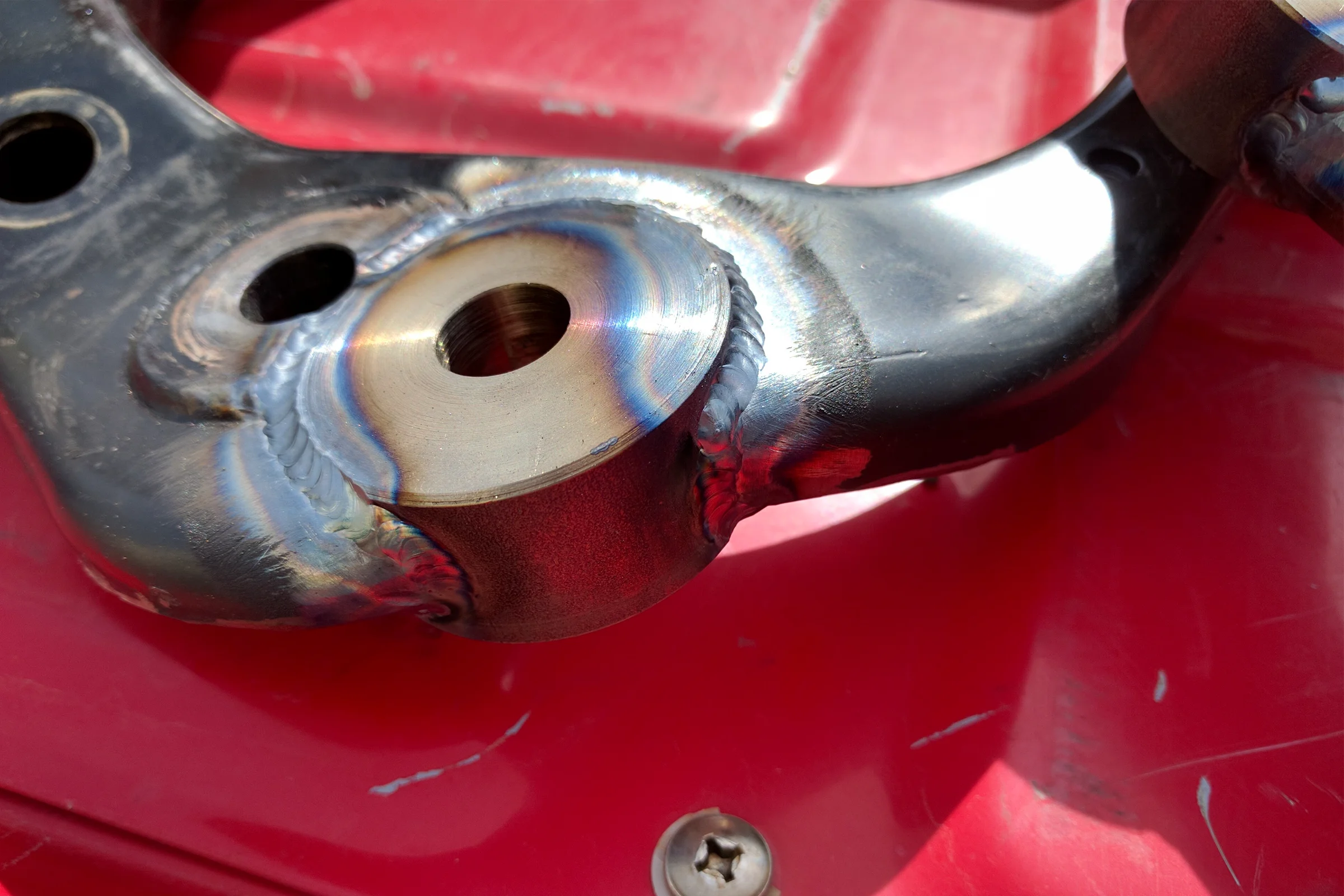
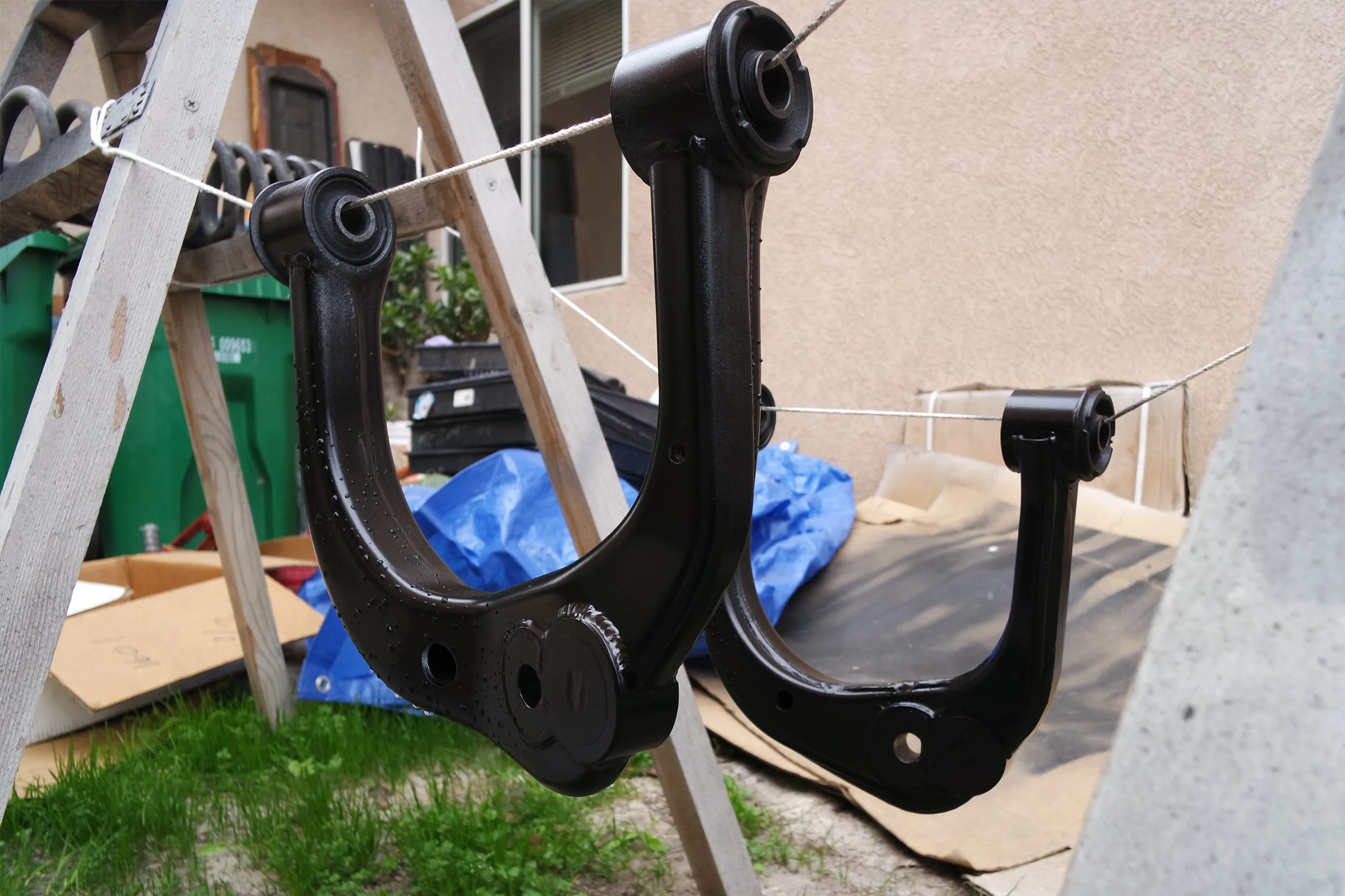
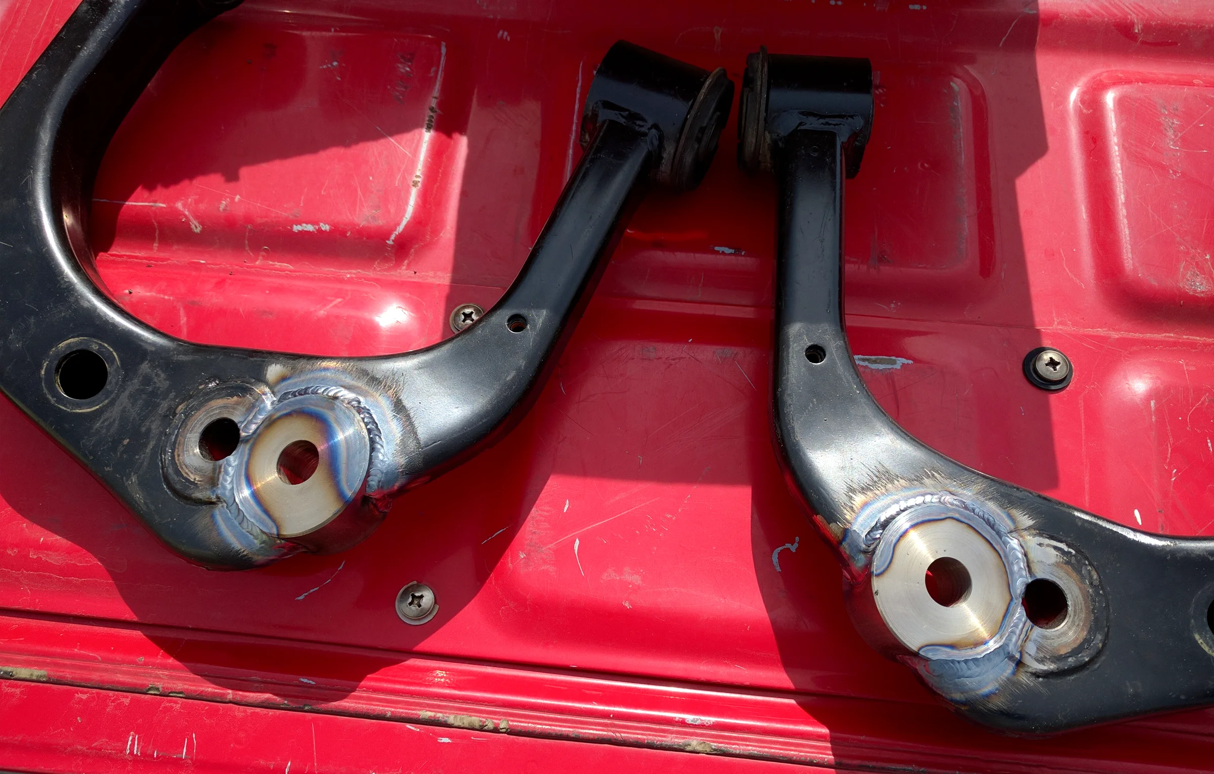
I only had a MIG welder in my shop, but I knew the application warranted TIG. The stamped steel control arm was significantly thinner than the solid mild steel ball joint disk I had turned on the lathe. Managing the heat input between these disparate thermal masses would have been difficult with MIG. There was a high risk of burning through the thin stamping before achieving adequate penetration on the solid disk. I outsourced the welding to a local welder to ensure structural integrity of the joint. He was impressed enough to ask about the process. The TIG welds came out perfect. Cleaned and painted both arms to a factory flat black finish.
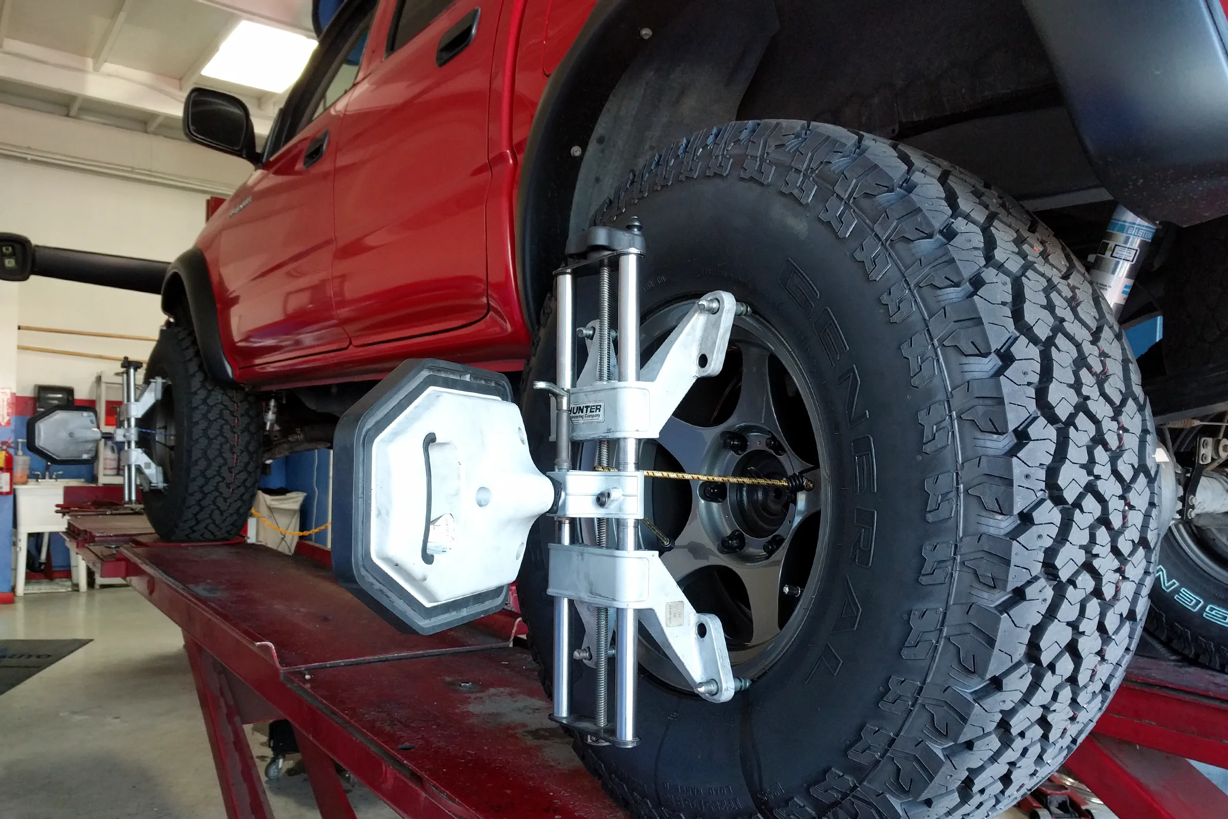
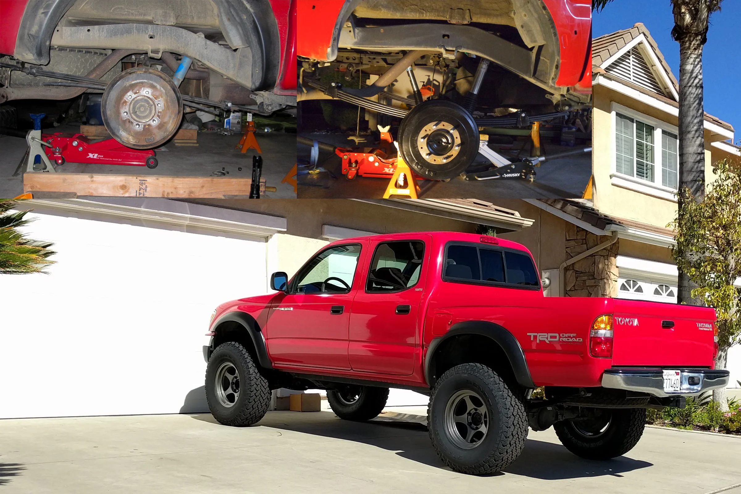
Installation and Alignment Validation
Installed both modified arms on the truck. Drove directly to the alignment shop and explained to the tech what had been done. Caster, camber, and toe all came into factory specification, with every adjustment bolt sitting in the middle of its adjustment range. Confirming the geometry correction worked exactly as expected.
Steering self-centering behavior returned to normal. The modified arms have been on the truck ever since taking abuse off road, with no issues and no regrets about not spending the $1,000 on the aftermarket units.