Voron
Architecture
Started by designing a CoreXY printer from scratch to incorporate the best available ideas at the time. Found the Voron project mid-design, recognized what they were doing right, contributed design feedback, and eventually built one of the most documented and modified Vorons in the community. The most interesting parts were not the deliberate decisions. They were the accidental ones.
Origin: Evaluating the Architecture
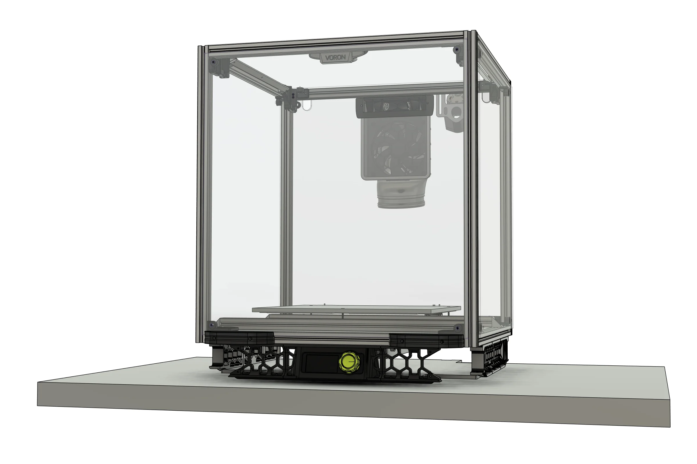
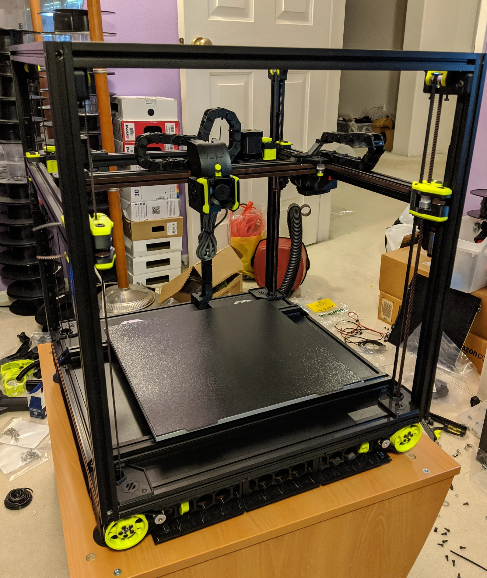
This wasn't about reinventing the wheel. After years of modifying existing printers the goal was to build one that deliberately incorporated the best available technologies at the time: CoreXY motion for fast non-mass-dependent movement, linear rails instead of rod-and-bearing for rigidity and precision, MIC6 cast aluminum tooling plate for a mechanically flat print surface that doesn't require active leveling, and an AC silicone heater for fast heat-up times. The one self-imposed requirement was maximum front and top access without compromising frame rigidity, which none of the existing designs prioritized.
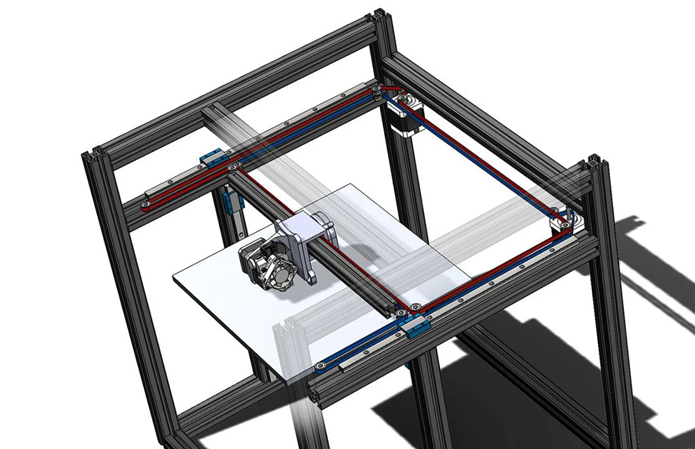
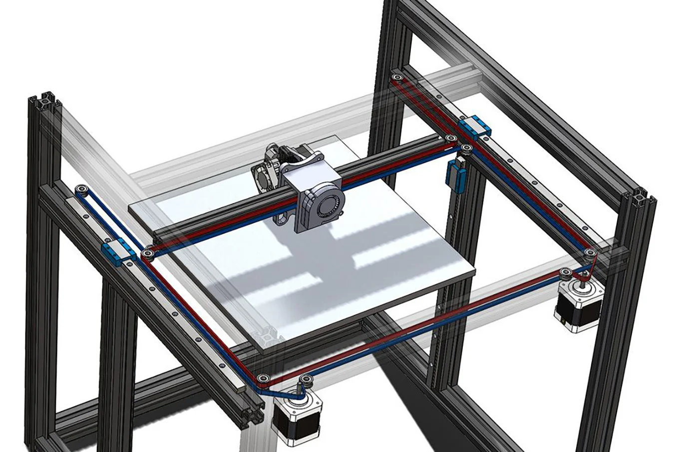
While developing the concept I came across the Voron project. Their flying gantry architecture was the thing that stood out. Traditionally Z is driven by two parallel motors which limits how independently each corner can be leveled. Voron solved this by running two controller boards together to drive four fully independent Z motors, one at each corner. The result was automatic four-point gantry leveling, and the MIC6 bed, the heaviest component, sitting stationary at the bottom of the frame. That combination hadn't seemed achievable before seeing it implemented. I shared my own concept with the community and got useful feedback. The creator of Voron noted unprompted that my gantry configuration looked like the V2.1 they already had in early development, the same rear crossbar position I had arrived at independently. Neither influenced the other. Two separate lines of thinking converging on the same answer is its own kind of validation.
From STL to Parametric CAD
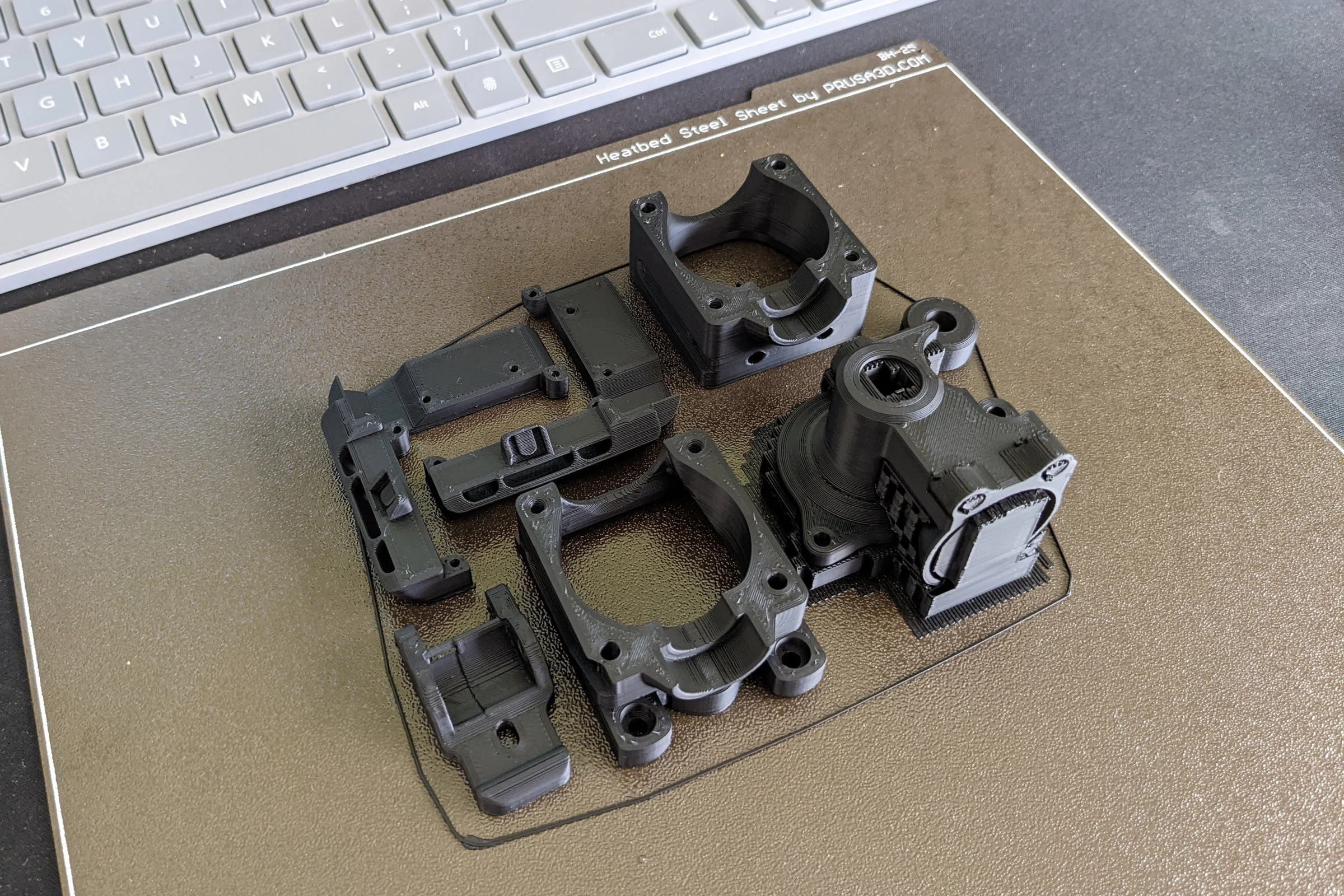
Same situation as the LulzBot program: only mesh files, no native CAD. Before cutting a single extrusion, I reverse-engineered the full Voron STL library into a parametric Fusion 360 assembly, cross-referenced against physical measurements from the machine. This wasn't optional. Lower-level modifications were planned from the start, including a full extruder redesign for 2.85mm filament, and a fully editable assembly was the prerequisite for all of it. Every custom part that followed was designed against that model.
The Non-Square Build: A Bug and a Better Design
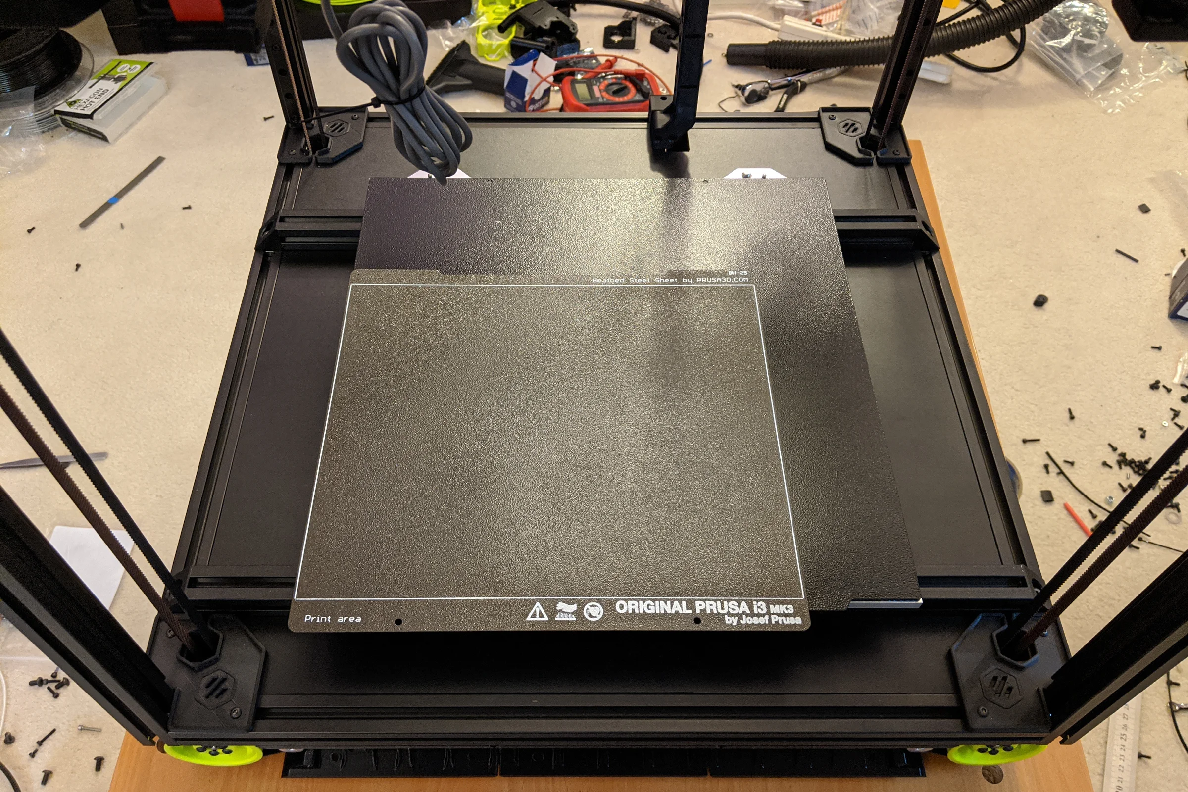
Standard Voron configurations are 250x250mm or 300x300mm. The stock 300x300mm build gives slightly less than 300mm of usable Y travel because the nozzle probe at the rear of the bed requires the gantry to travel past the bed edge, bringing actual usable Y down to around 285mm. That was unacceptable. I also wanted nozzle travel beyond the bed boundary on all four sides for outside-bed purging and overtravel without losing print area. There is no engineering reason the printer footprint needs to match the square geometry of the bed. I configured 310mm X and 315mm Y and ran those numbers through Voron's frame rail length configurator.
I was apparently the first person to generate a non-square configuration. After the custom-cut aluminum extrusions arrived, the two bed mounting rails that should run front-to-back were clearly the wrong length. The configurator had output the width dimension for both. My bed rails had to run side to side. I reported the bug to the development team. They acknowledged it but noted that since no one else would build a non-square printer it was low priority. I proceeded anyway.
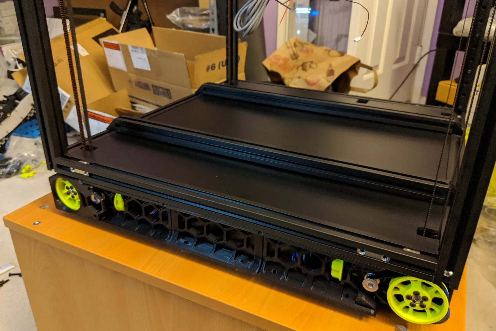
As the frame went together, the side-to-side rail orientation turned out to look better. The proportions were cleaner. I kept it, and that accident set off a chain of downstream design decisions that each turned out better than the original plan would have produced.
MIC6 Bed: Sourced from Remnant Stock, Milled, Accidentally Optimal
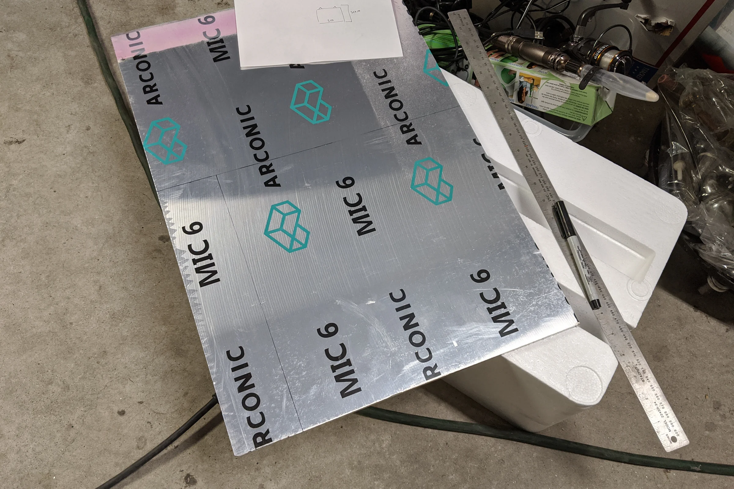
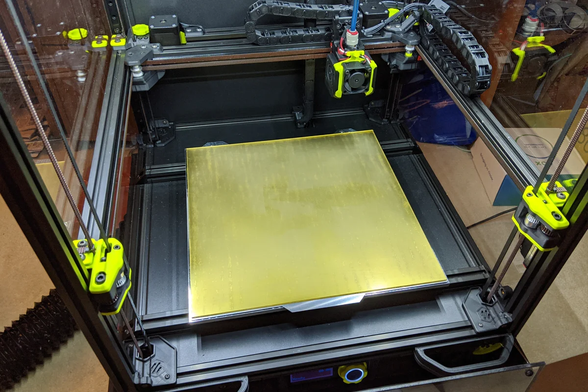
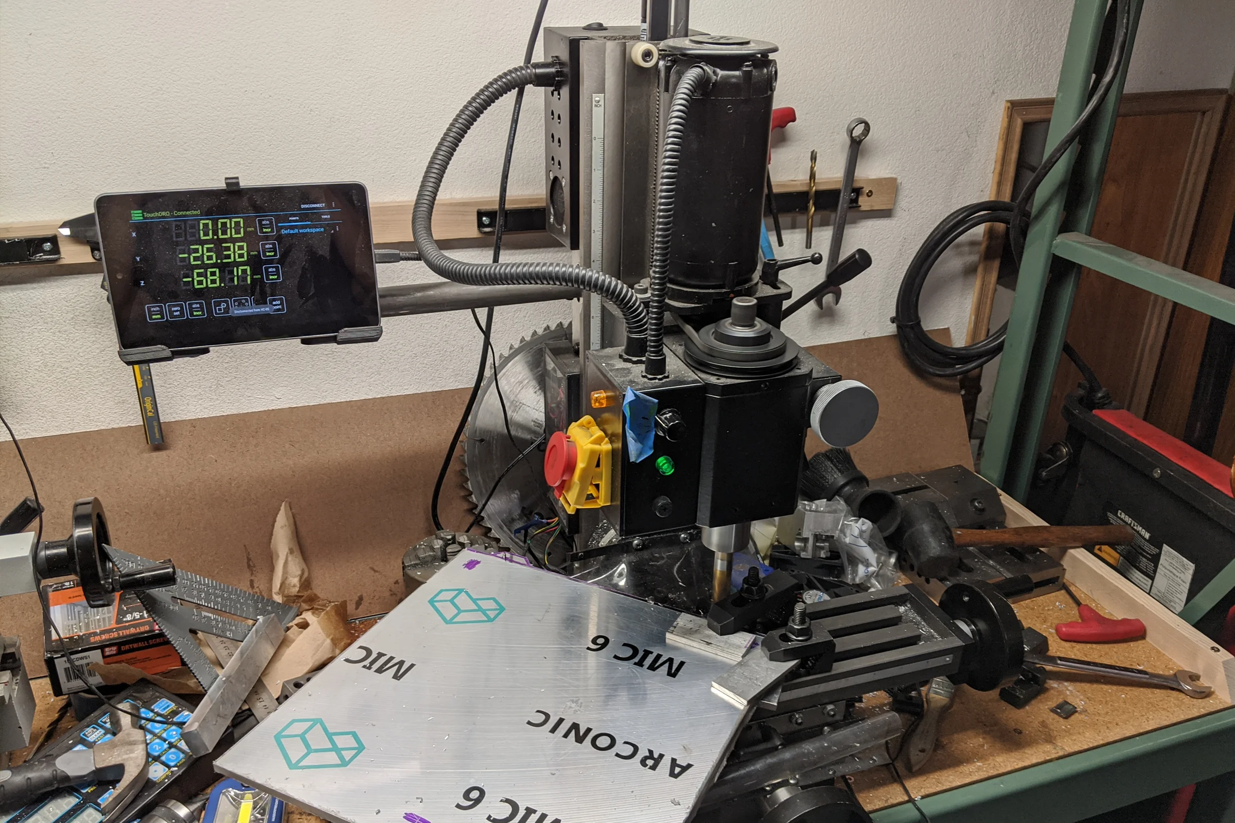
Rather than ordering a MIC6 plate cut to spec from an online supplier at high shipping cost, I went to my local industrial metal supplier's remnant section and found MIC6 plate, slightly thinner than recommended, at a fraction of the cost. Bought it and milled it myself.
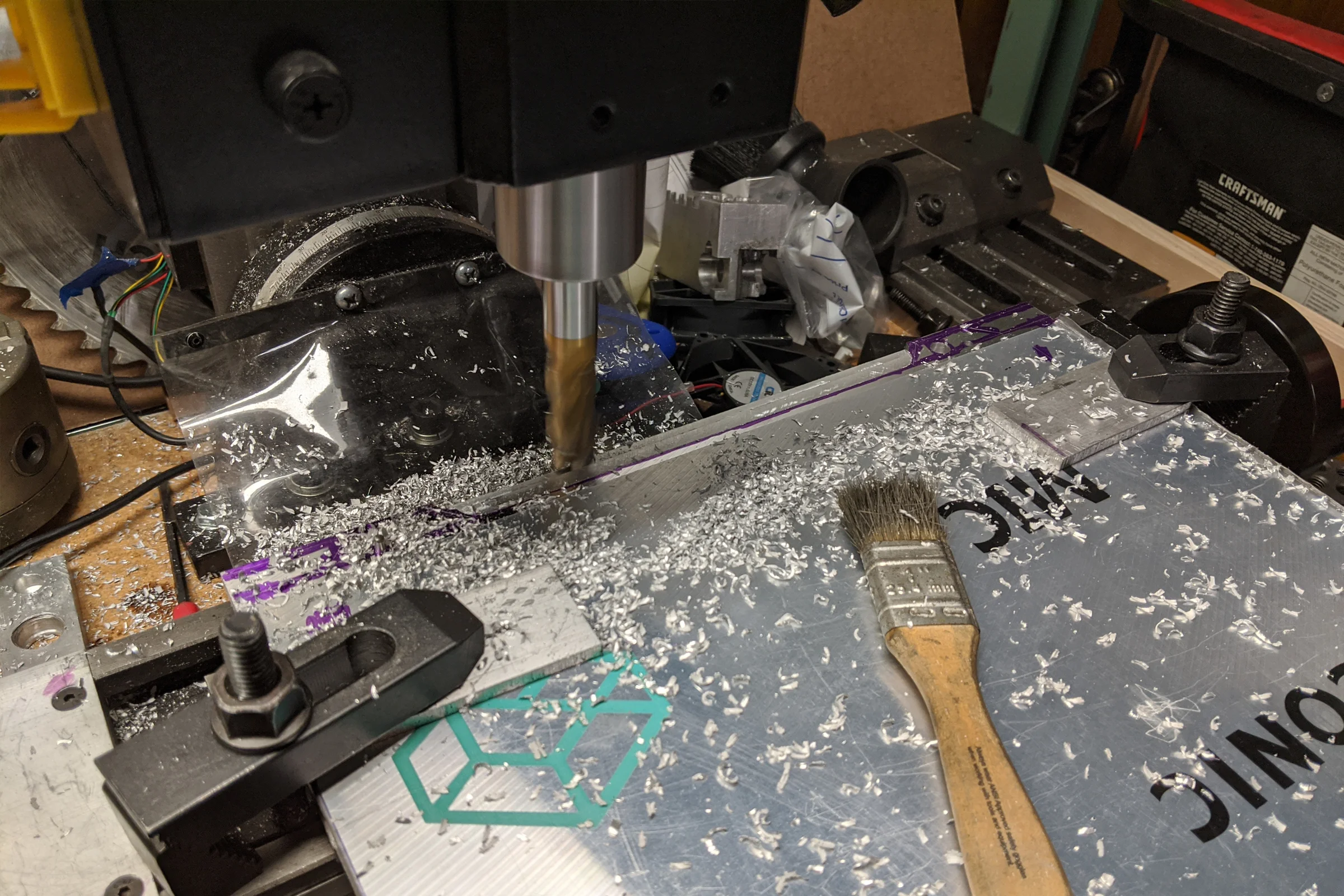
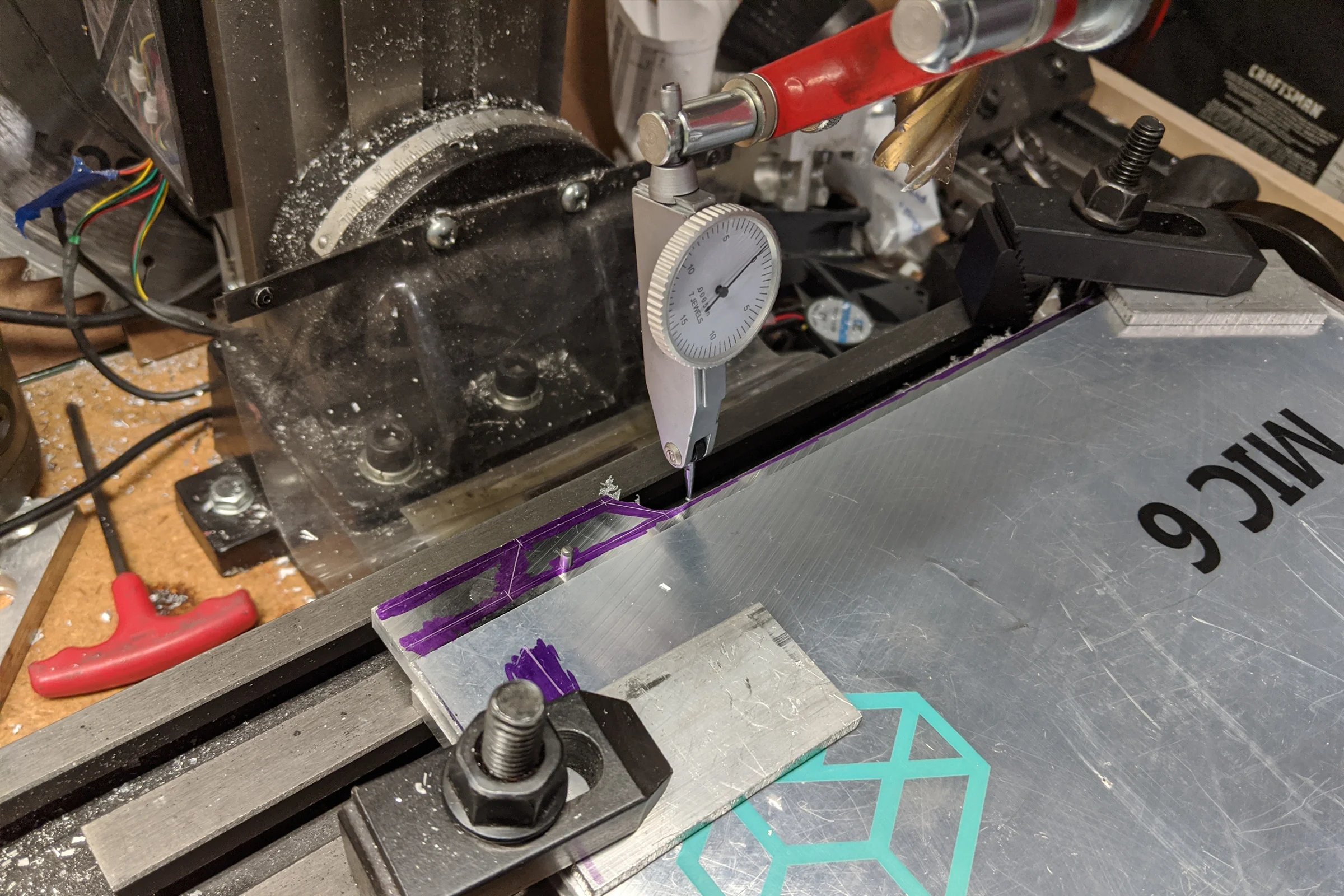
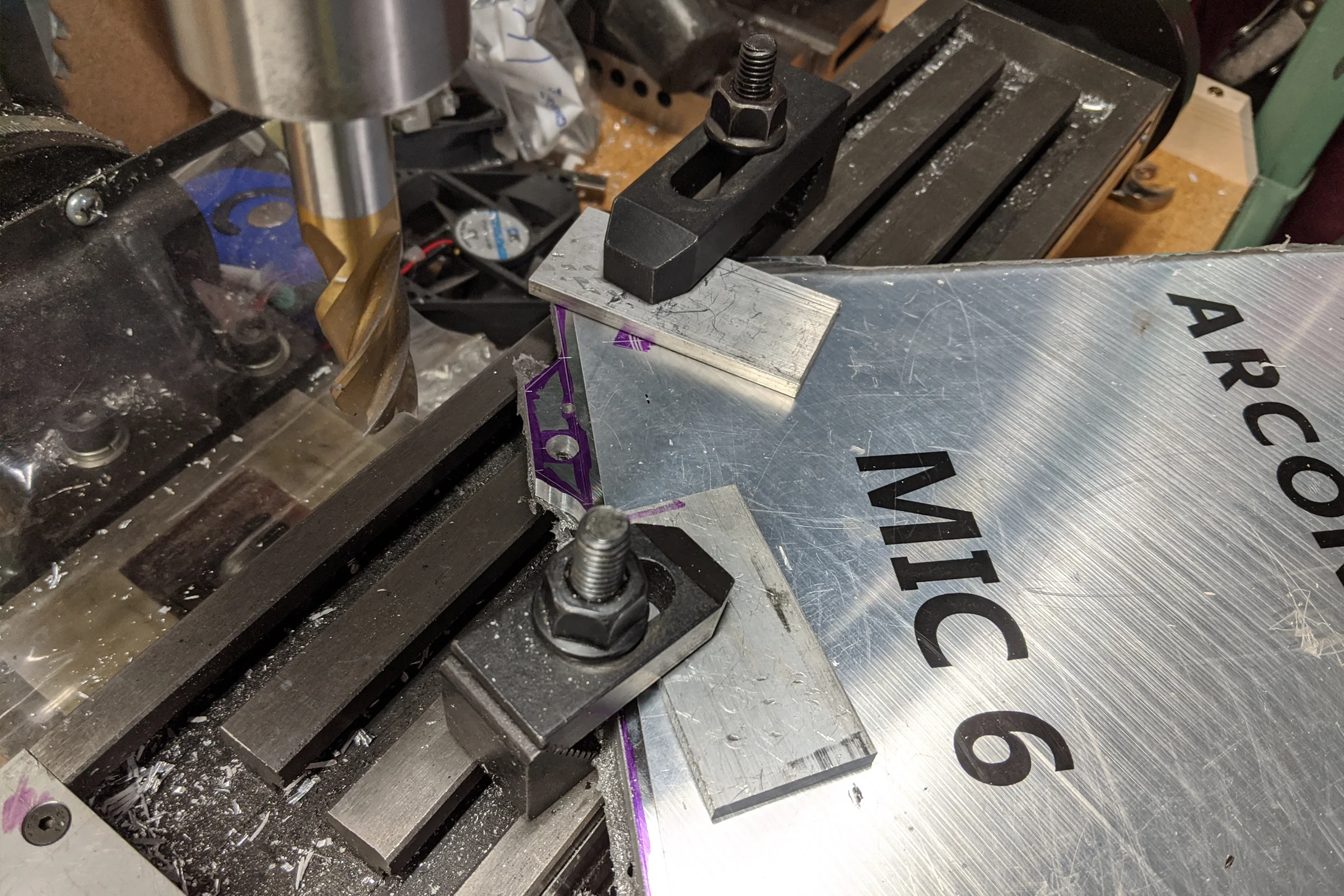
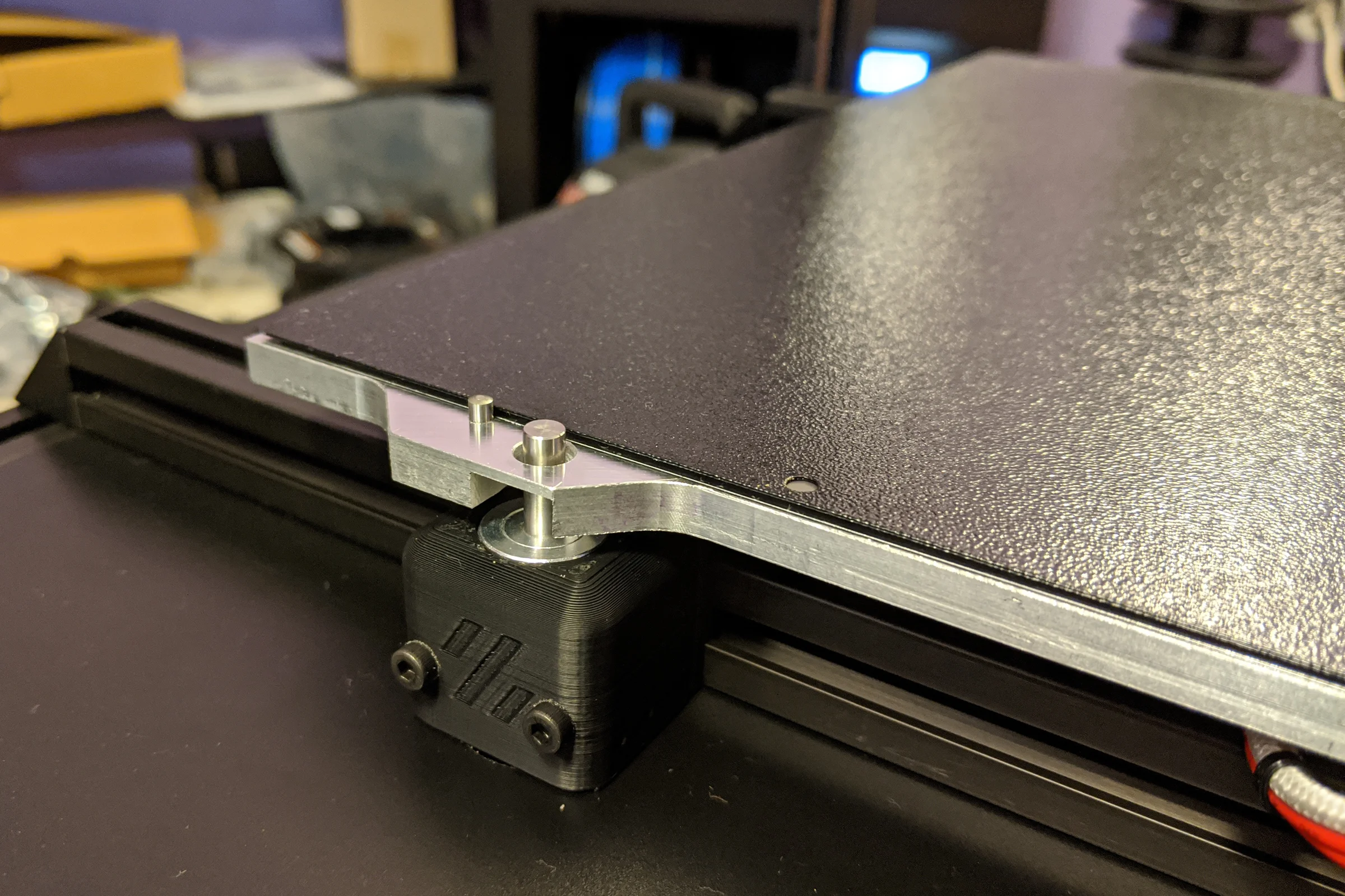
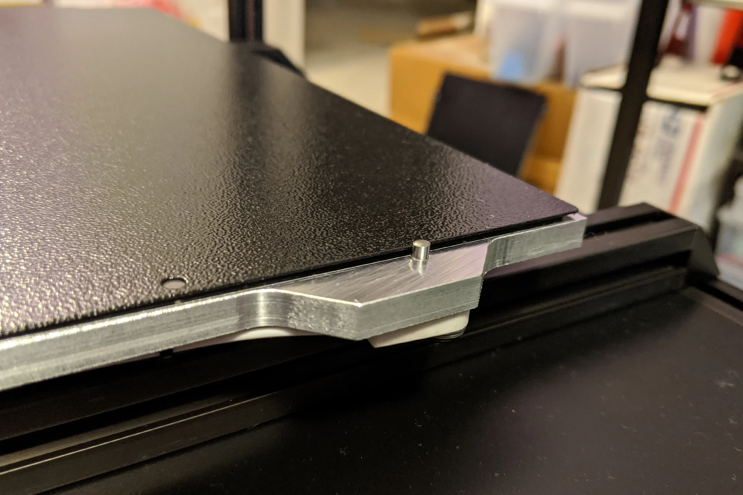
Having my own mill opened up decisions no one ordering a pre-cut plate could make. I added two extending tabs at the rear of the bed. The Z probe nozzle pin passes through those tabs, distinctive on a part most builders have no ability to customize. I also added locating pins to the tabs as a repeatable datum for the magnetic flex plate, every removal and replacement snaps back to the same position without re-tramming.
The side-to-side rail accident had an unexpected structural consequence. Voron bed design specifies four corner mounting holes from the early versions. Later it was recognized that three-point kinematic mounting is superior for a rigid flat surface, three points define a plane with no over-constraint. The problem was that every existing build had MIC6 already cut for four corner holes, so the community kept using four holes but only bolting three, leaving one corner on a long cantilever.
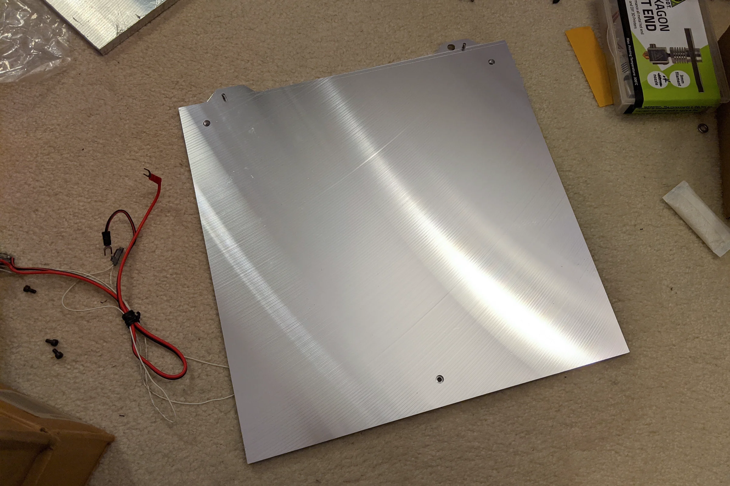
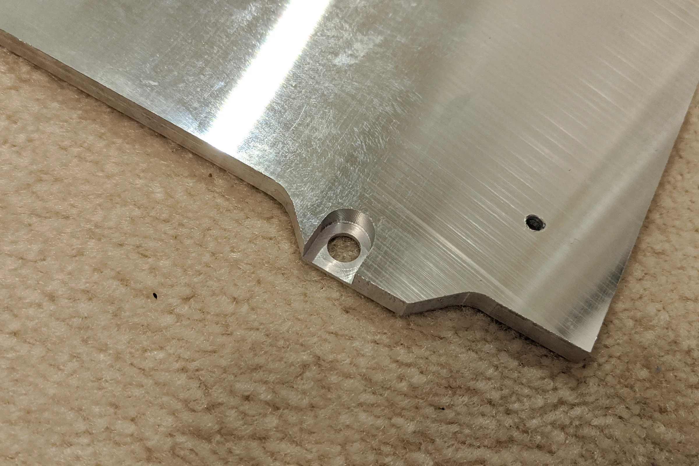
Because my non-standard side-to-side rails required the bed to be mounted differently, I was able to place the three mounting points where the geometry actually called for them. Two rear points and one centered front point: a perfect equilateral triangle from the center of the bed. The best possible kinematic configuration, arrived at entirely by accident.
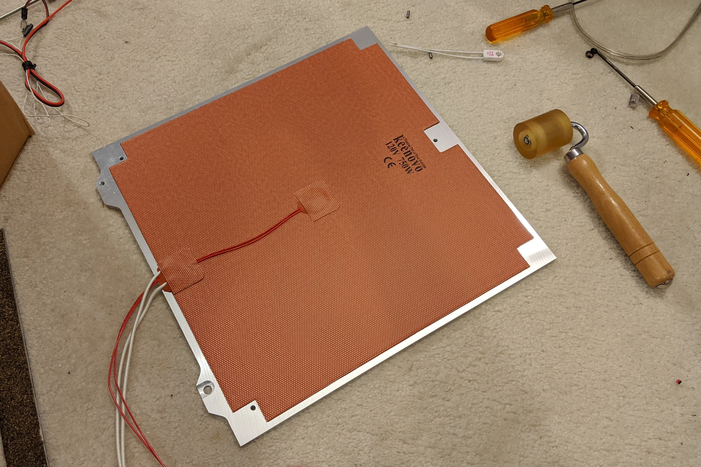
Three mounting points at custom positions meant no standard AC silicone heater would fit. I contacted the Chinese manufacturer directly, sent my CAD drawing, and asked if they could produce a custom heater with three mounting holes punched at my exact coordinates. They said yes at no extra charge. The custom heater arrived matching the drawing exactly.
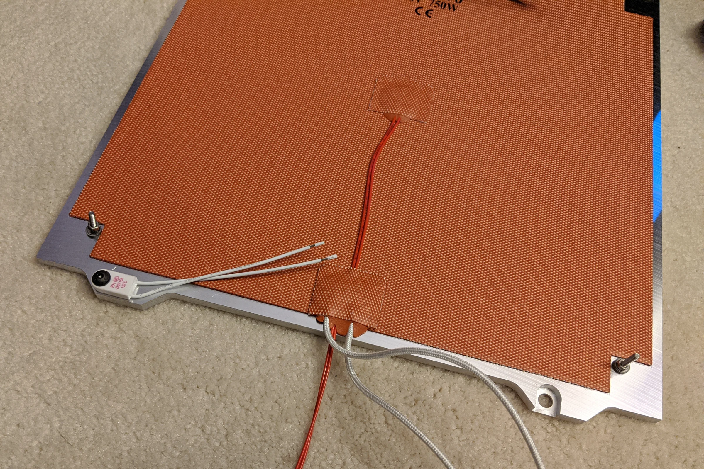
The thermal fuse that must be bolted in direct contact with the underside of the bed is normally accommodated by making the heater smaller than the bed, leaving the edges exposed. Edges are where the most heating loss occurs. With the tabs extending beyond the print area, the thermal fuse could be mounted to the tab undersides, allowing my custom heater to cover the bed essentially edge to edge.
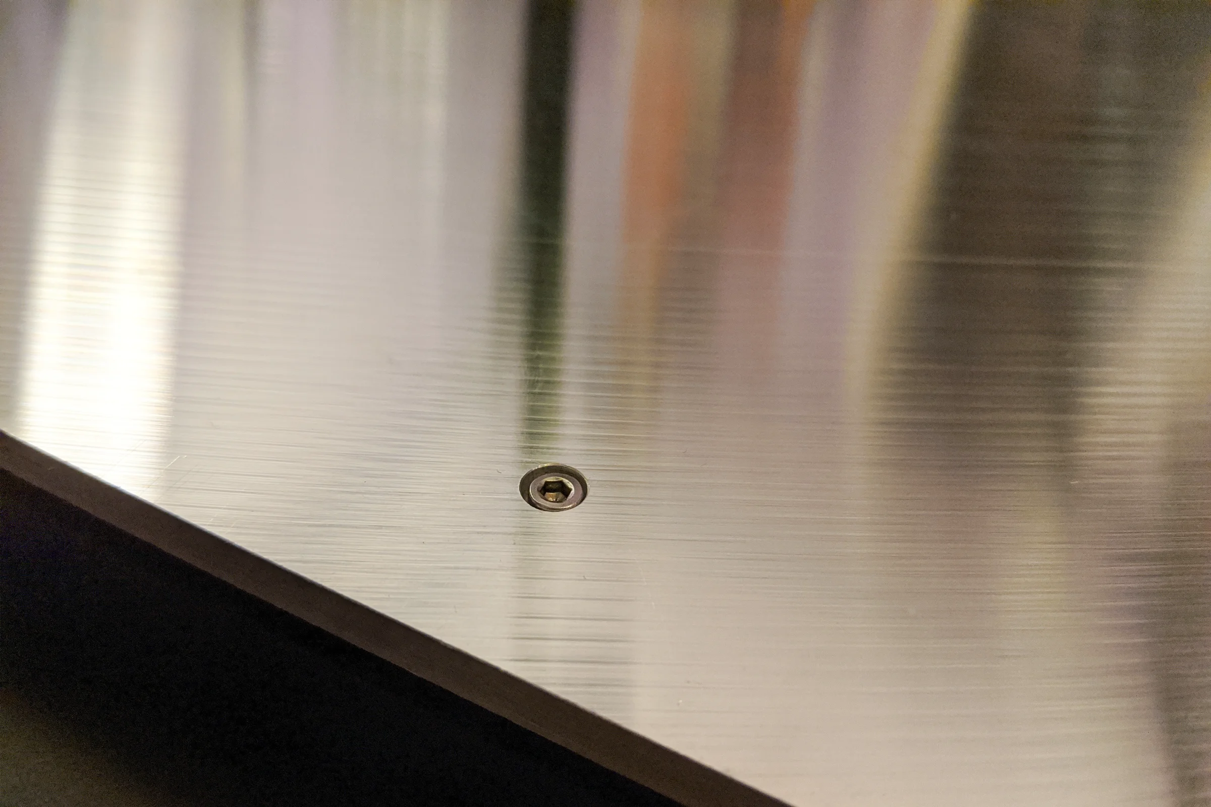
The two non-reference mounting points use slotted holes in the radial direction from the reference point, with fiber washers between the bolt hardware and the plate on both sides. The fiber washers prevent metal-on-metal contact so the MIC6 can thermally expand and slide slightly in the slot direction without any constraint on flatness. The reference point at rear-right nearest the nozzle probe is rigidly bolted: no slot, no washers, stainless hardware directly through.
Modular Printhead: 1.75mm or 2.85mm, Any Hotend
The Voron was originally designed as a Bowden system running 1.75mm filament. The first modification was converting it to 2.85mm, driven by economics: the LulzBot printhead business had accumulated a large free stash of 2.85mm material, and retail stores were clearing 2.85mm inventory at pennies on the dollar as the market converged on 1.75mm. The material cost difference was large enough to design around. The Bowden setup made this conversion relatively straightforward since the extruder motor sat outside the printhead on the frame, far from the space-constrained carriage.
During that 2.85mm Bowden redesign, the nozzle datum problem was solved almost as a side effect. Most Voron users never think about nozzle position consistency across hotends because the Z probe handles it in software: if a different hotend changes the nozzle height, the probe recalibrates automatically on the next print. That software compensation is sufficient for anyone running one hotend configuration permanently.
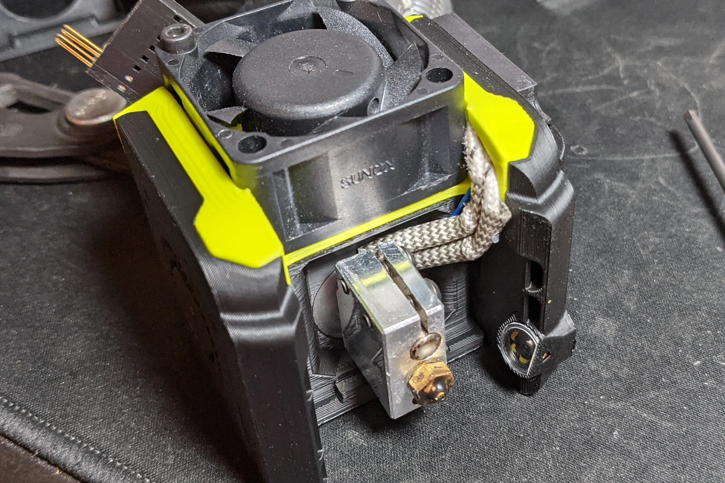
It was already clear at this stage that a fixed on-gantry nozzle camera was the next project. A camera has a fixed focal point and a fixed field of view. Software Z compensation cannot move an optical system. If the nozzle datum shifts between hotend swaps, the camera's calibrated view breaks regardless of what the firmware does. The nozzle position had to be physically identical across every hotend configuration.
The solution was to build the compensation into the hardware itself: each hotend housing is designed to a consistent nozzle datum by compensating for its own length variation, so every housing drops the nozzle to exactly the same position regardless of hotend geometry.
The nozzle datum solution wasn't just a fix. It was the prerequisite that made the nozzle cam project possible.
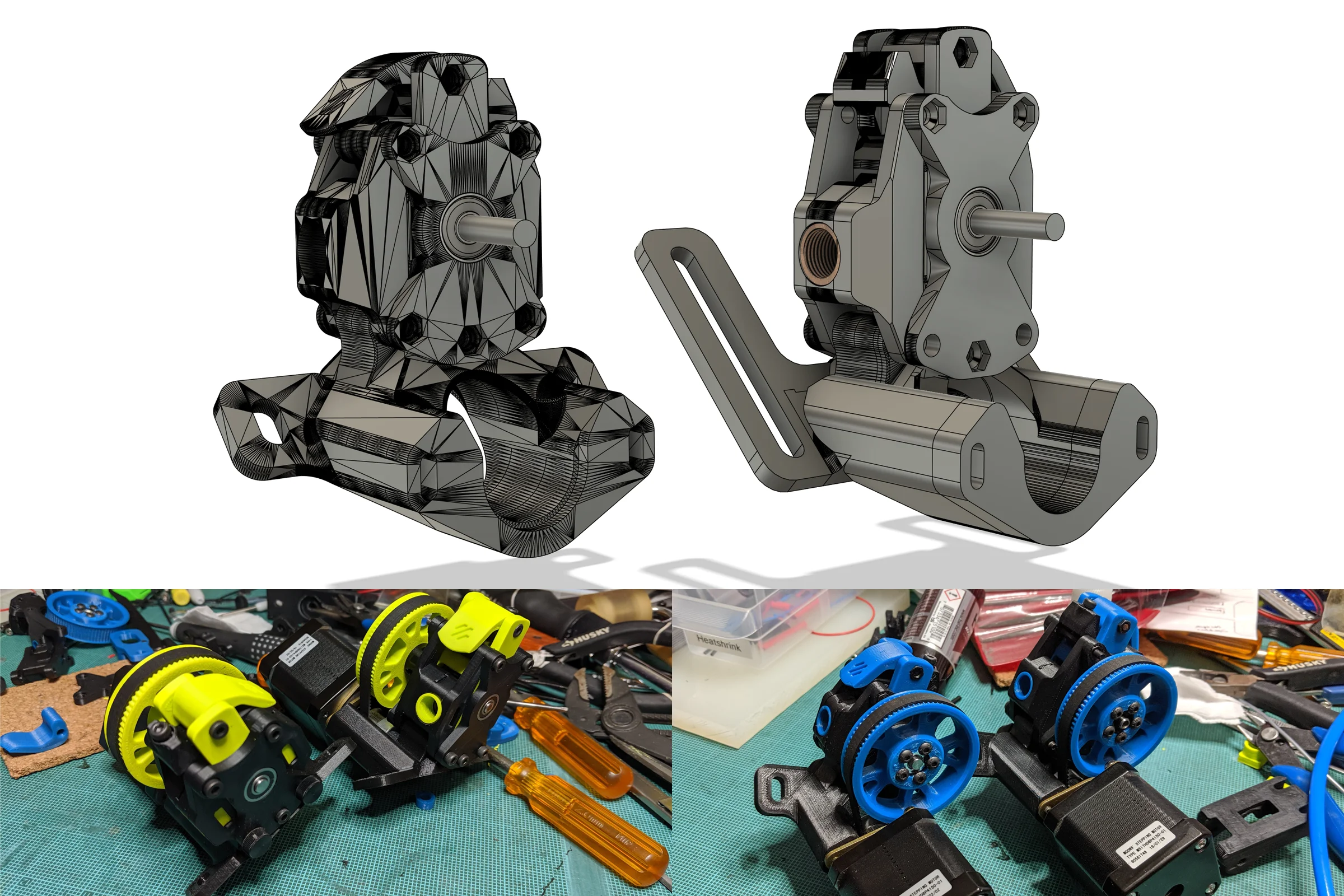
Nozzle cam development was underway when the direct drive problem was solved. The community had been working out whether miniaturized direct drive was achievable on the Voron's compact carriage without sacrificing the mass advantage that made Bowden worth using in the first place. The answer was NEMA14 stepper motors with high planetary gear reduction, delivering enough torque from a fraction of the weight and volume of a standard NEMA17. For 2.85mm filament running at significantly higher back-pressure than 1.75mm, that gear ratio wasn't a nice-to-have — it was the difference between viable and not. Being the only person in the community running 2.85mm meant there was more at stake in getting the torque math right than anyone else working on it.
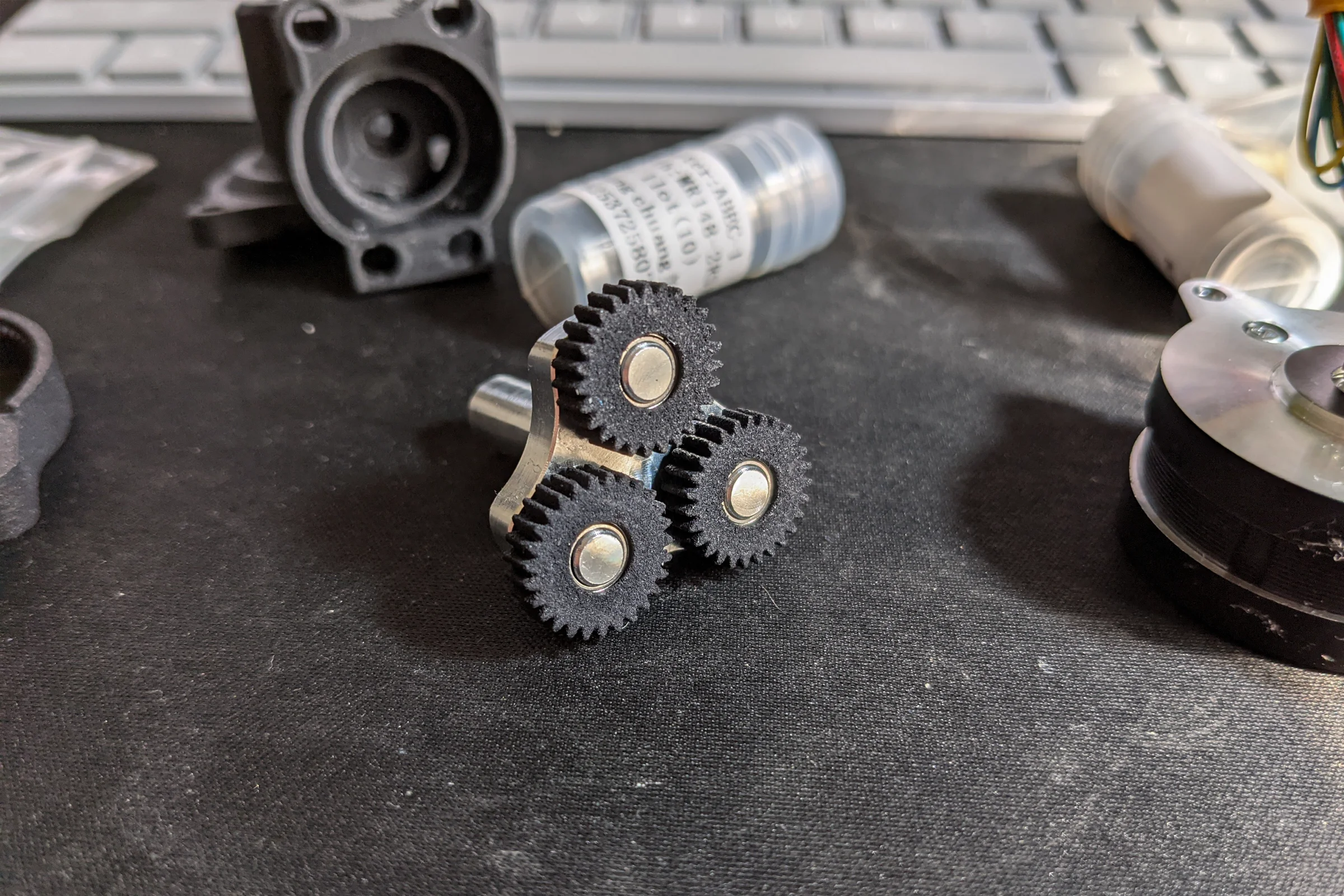
The Orbiter extruder was the right platform: open source, high planetary reduction, NEMA14 native. Modifying it for 2.85mm required designing around two fixed geometric constraints simultaneously — the CNC planetary gear hub from a community group buy that couldn't be changed, and the dual filament drive gears, which are significantly larger in the 2.85mm version than their 1.75mm counterparts. Both were immovable. Everything else was redesigned around them.
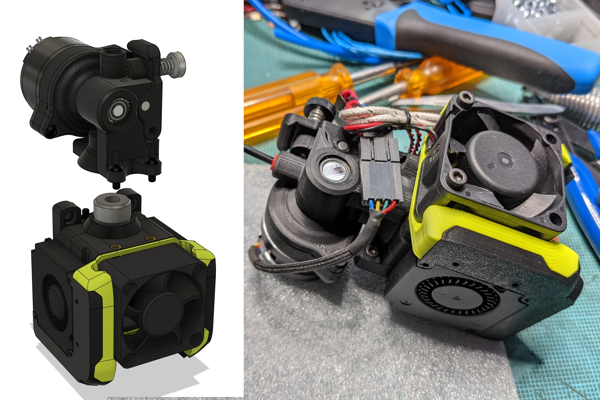
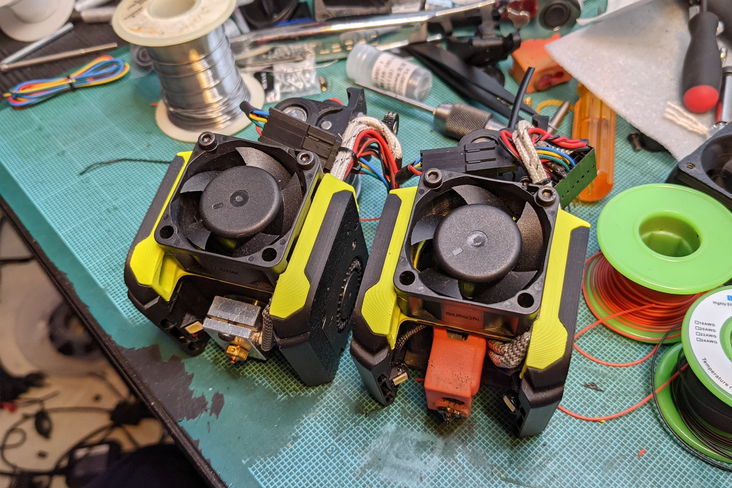
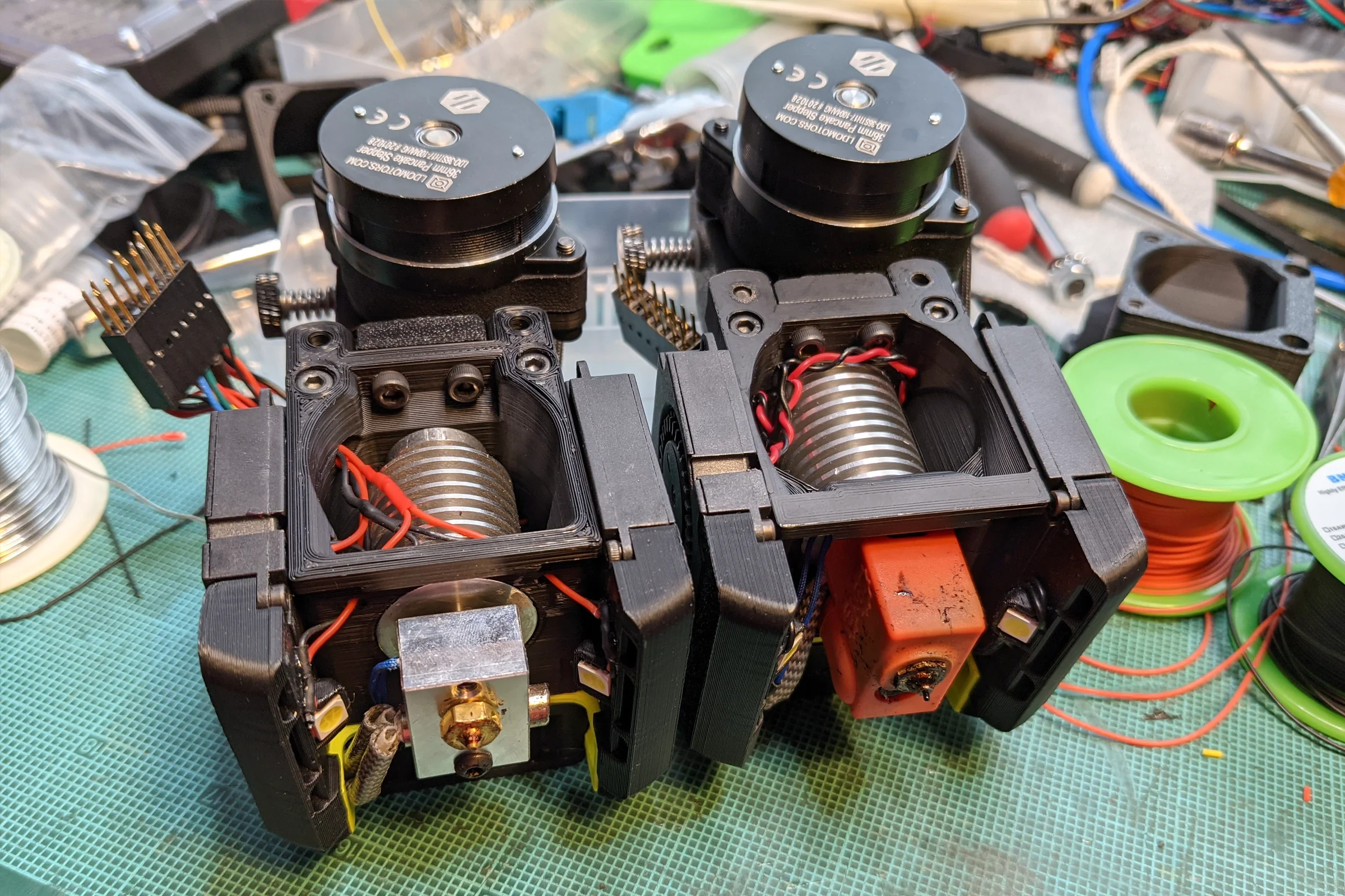
Incorporating direct drive as a third modular configuration — alongside the existing Bowden 1.75mm and Bowden 2.85mm setups — meant the direct drive extruder now lived on the printhead carriage rather than on the frame. The nozzle datum system already handled the physical swap. What it created was a firmware problem nobody else in the community had: each combination of filament diameter and hotend type required its own firmware profile, with configuration differences significant enough that a simple variable swap was insufficient. The hardware modularity that made the machine flexible multiplied the firmware management problem directly, and there was no community solution to reference because nobody else was running this combination. A custom Octoprint plugin script handles the firmware config file swap automatically in two clicks when changing configurations. Swapping between hotend configurations takes seconds on both the hardware and software side.
Electronics, Fume Extraction, and Integrated Systems
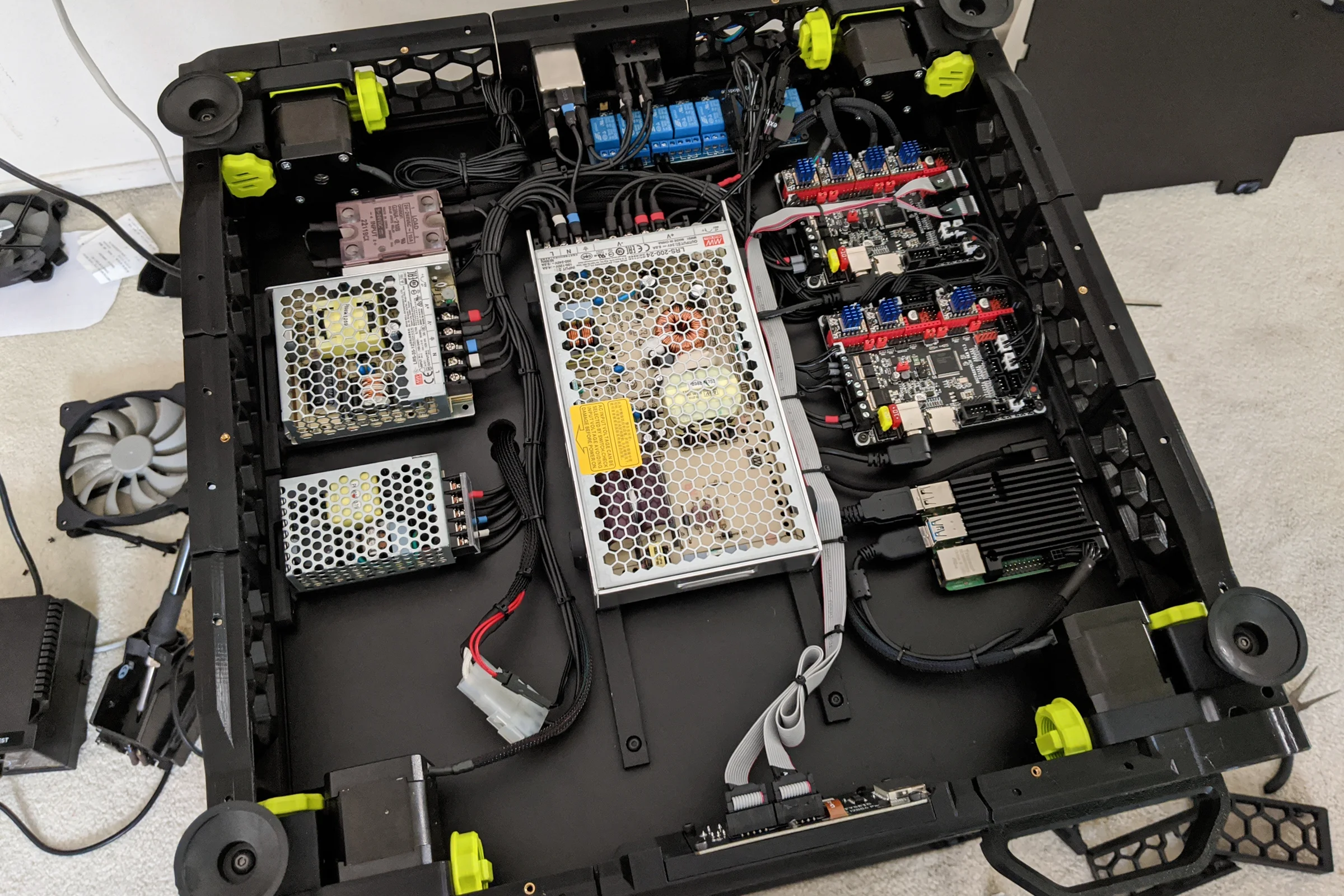
The electronics bay uses custom mounting plates sized to the exact footprint of each board, with separated voltage rails and a 12-channel relay system for software-controlled switching of lighting, fans, and printer power, all accessible from the bottom of the machine. Every wire bundle runs a dedicated routed path, no unnecessary crossings, secured at deliberate intervals. The underside wiring became one of the most commented-on aspects of the build, the direct result of treating it as a design problem rather than an afterthought.
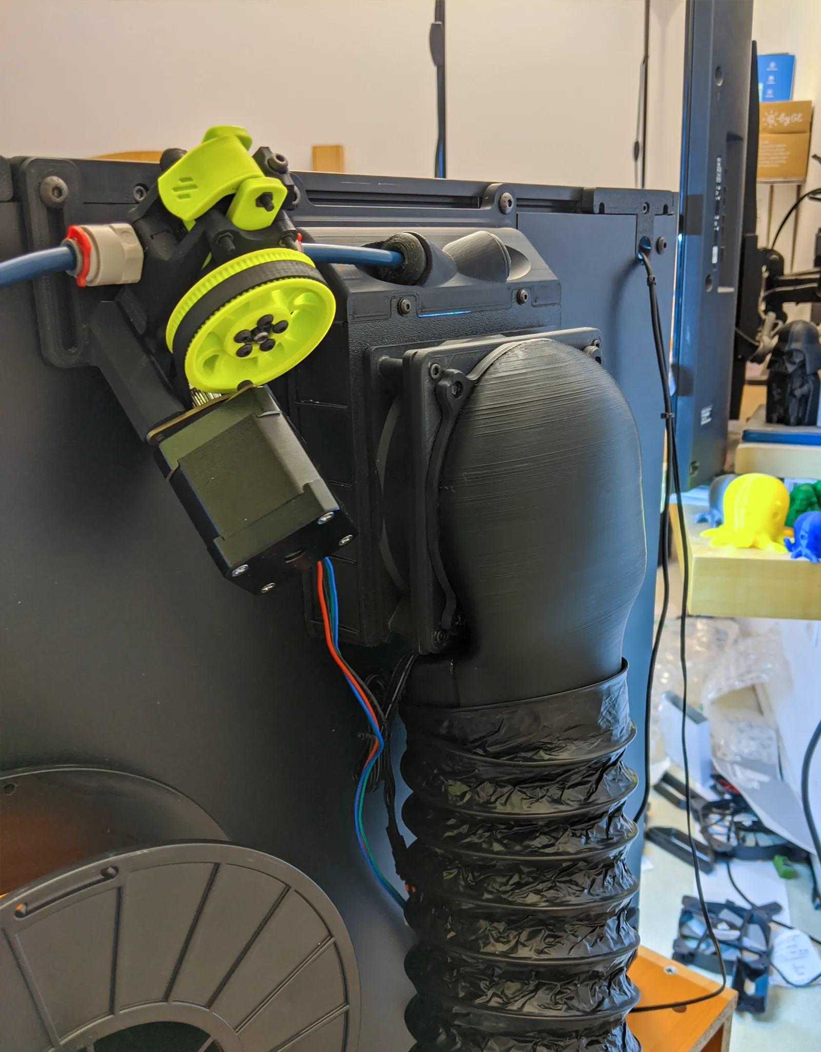
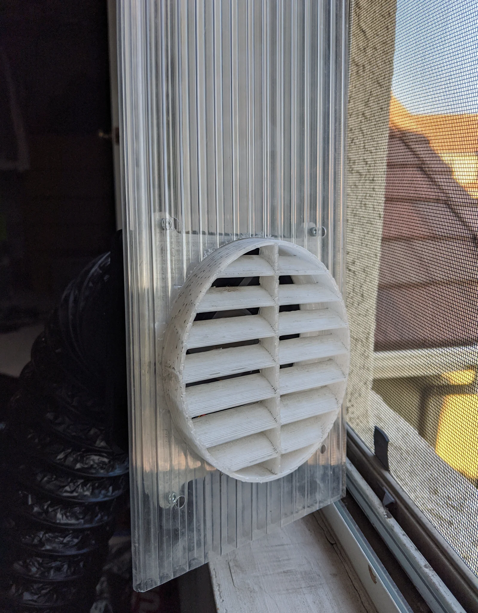
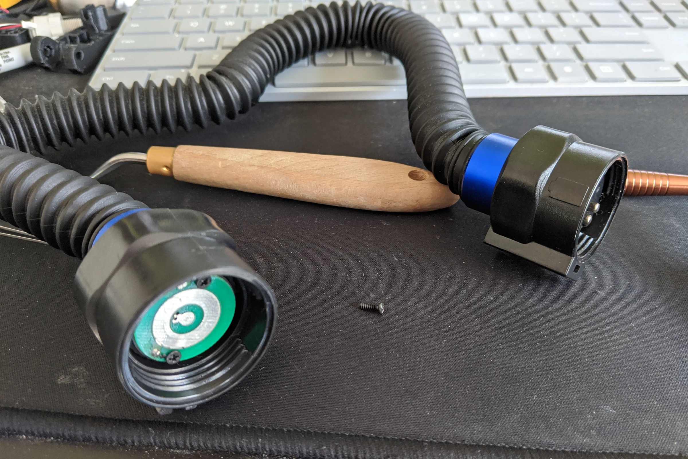
The fume extraction system was built from scratch because printing ABS in a room requires actual extraction, not filtration. Voron's stock activated carbon filter still vents into the room and asks a lot from a small amount of filter media. I built a full exhaust system ducted outside through a window that can still fully close around the duct. A 140mm fan on the window side ensures consistent push-pull exhaust pressure. Powering that external fan without another hanging wire across the room required a creative solution: I salvaged magnetic contact pins and PCBs from cheap Lowe's flashlights, cheaper to buy the whole flashlight than to source the magnetic contact components separately, and built them into the air duct as power contacts. The external fan draws power directly from the printer through those contacts inside the duct. The full duct system mounts magnetically on both ends, connecting or disconnecting in seconds.
Community Recognition and the Nozzle Camera
The build was documented throughout as a community build log. The non-square configuration, the custom milled bed with the nozzle probe tab (visually distinctive enough to attract sustained attention on its own), the modular printhead, and the wiring discipline combined into one of the most widely recognized Voron builds in the community. Not because of the earlier design suggestions, but from showing the work and explaining the reasoning. Serial number V2.180, under the 200th registered build, with all the custom modifications already incorporated before submission.
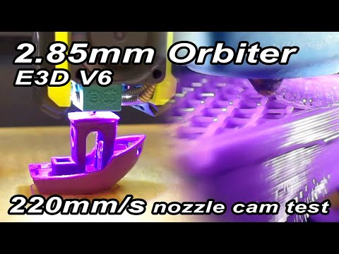
The final addition was a miniature nozzle monitoring camera built from an affordable USB endoscope. The complete methodology was published openly on YouTube rather than as a downloadable STL file, the intent was for people to understand the approach well enough to evolve it, not just reproduce it. The design spread widely through the community. CNC Kitchen, one of the most prominent 3D printing channels, credited the design by name and built their own from it. Obico's official nozzle camera installation documentation credits the YouTube guide as a primary source. The concept was later commercialized by others as a dedicated product category. Full documentation on the Nozzle Camera System page.